How to measure with an electronic tester (multimeter)
The home craftsman periodically needs to measure the parameters of the circuits. Check what voltage is currently in the network, whether the cable is frayed, etc. For these purposes, there are small devices - multimeters. With their small size and cost, they can measure various electrical parameters. We will talk about how to use a multimeter further.
The content of the article
External structure and function
Recently, specialists and radio amateurs mainly use electronic models of multimeters. This does not mean that the turnouts are not used at all. They are irreplaceable when, due to strong interference, electronic ones simply do not work. But in most cases, we are dealing with digital models.
There are different modifications of these measuring devices with different measurement accuracy, different functionality. There are automatic multimeters in which the switch has only a few positions - they choose the nature of the measurement (voltage, resistance, current) and the device selects the measurement limits itself. There are models that can be connected to a computer. They transfer the measurement data directly to a computer, where they can be saved.
Automatic multimeters on a scale have only types of measurements
But most do-it-yourselfers use inexpensive, mid-range models (with 3.5 bit depth, which provides 1% accuracy). These are common dt multimeters 830, 831, 832, 833.834, etc. The last figure shows the "freshness" of the modification. Later models have wider functionality, but for home use these new features are not critical. Working with all these models is not much different, so we will talk in general about techniques and procedures.
The structure of an electronic multimeter
Before using the multimeter, let's study its structure. Electronic models have a small LCD screen that displays the measurement results. There is a range switch below the screen. It rotates on its own axis. The part with a red dot or arrow indicates the current type and range of measurements. Around the switch there are markings by which the type of measurements and their range are set.
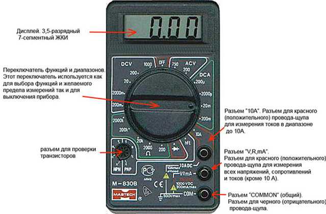
General device of the multimeter
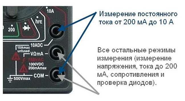
Below on the body there are sockets for connecting probes. There are two or three sockets depending on the model, there are always two probes. One is positive (red), the other negative is black. The black test lead always connects to the connector labeled "COM" or COMMON or labeled "ground". Red - to one of the free slots. If there are always two connectors, there are no problems, if there are three sockets, you need to read in the instructions for what measurements to insert the "plus" probe into which socket. In most cases, the red test lead is plugged into the middle socket. This is how most measurements are taken. The upper connector is necessary if the current is up to 10 A to be measured (if more, then also to the middle slot).
Where to connect the multimeter probes
There are models of testers in which the sockets are not located on the right, but at the bottom (for example, the Resant DT 181 multimeter or Hama 00081700 EM393 in the photo). There is no difference when connecting in this case: black for the socket with the inscription "COM", and red according to the situation - when measuring currents up to 200 mA to 10 A - in the far right socket, in all other situations - in the middle one.
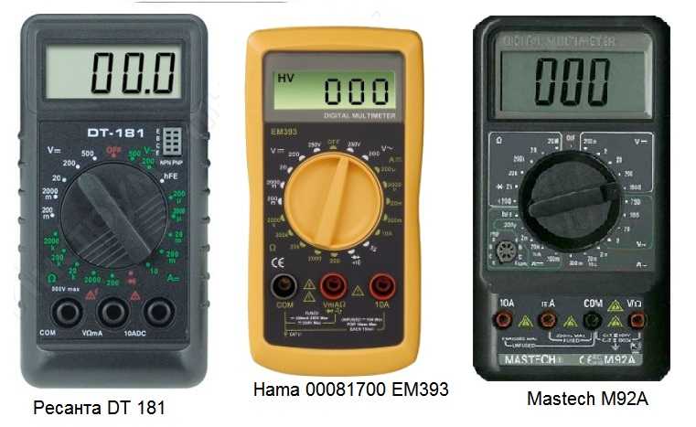
Probe sockets on multimeters can be located at the bottom
There are models with four connectors. In this case, there are two sockets for measuring current - one for microcurrents (less than 200 mA), the second for a current from 200 mA to 10 A. Having understood what and why is in the device, you can begin to figure out how to use a multimeter.
Switch position
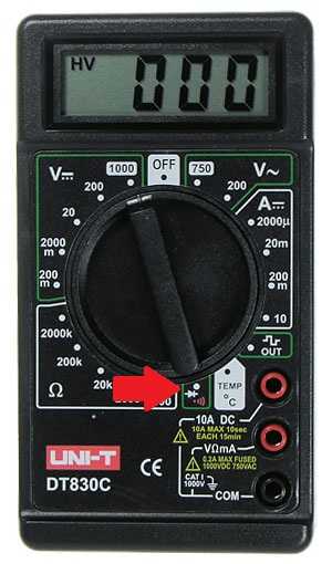
The measurement mode depends on which position the switch is in. There is a dot at one of its ends; it is usually tinted with white or red. This end indicates the current mode of operation. In some models, the switch is made in the form of a truncated cone or has one pointed edge. This sharp edge is also a pointer. To make it easier to work, you can apply bright paint to this pointing edge. It could be nail polish or some kind of abrasion resistant paint.
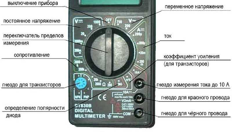
Position of the measuring range switch on the multimeter
By turning this switch you change the operating mode of the device. If it stands straight up, the device is turned off. In addition, there are the following provisions:
- V with a wavy line or ACV (to the right of the "off" position) - AC voltage measurement mode;
- A with a straight line - DC current measurement;
- A with a wavy line - definition of alternating current (this mode is not available on all multimeters, in the above photos it is not);
- V with a straight line or the inscription DCV (to the left of the off position) - for measuring DC voltage;
- Ω - resistance measurement.
There are also provisions for determining the gain of transistors and determining the polarity of diodes. There may be others, but their purpose should be sought in the instructions for a particular device.
Measurements
The use of an electronic tester is convenient because you do not need to look for the desired scale, count the divisions, determining the readings. They will be displayed on the screen with an accuracy of two decimal places. If the measured value has polarity, the minus sign will also be displayed. If there is no minus, the measurement is positive.
How to measure resistance with a multimeter
To measure resistance, move the switch to the zone marked with the letter Ω. We choose any of the ranges. We apply one probe to one input, the second to the other. Those numbers that will appear on the display are the resistance of the element you are measuring.
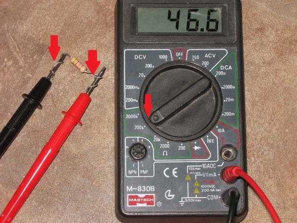
How to use a multimeter to measure resistance
Sometimes the screen does not display numbers. If "jumped out" 0, then you need to change the measurement range to a smaller one. If the words "ol" or "over" are highlighted, there is "1", the range is too small and should be increased. That's all the tricks for measuring resistance with a multimeter.
How to measure current
To select the measurement mode, you must first determine the DC or AC current. There can be problems with measuring AC parameters - this mode is not available on all models. But the procedure is the same regardless of the type of current - only the position of the switch changes.
D.C
So, having decided on the type of current, set the switch. Next, you need to decide which socket to connect the red probe to. If you do not even know approximately what values to expect, so as not to accidentally burn the device, it is better to first install the probe in the upper (leftmost in other models) socket, which is labeled "10 A". If the reading is small - less than 200 mA, move the probe to the middle position.
The situation is exactly the same with the choice of the measurement range: first, set the maximum range, if it turns out to be too large, switch to the next smaller one. So until you see the readings.
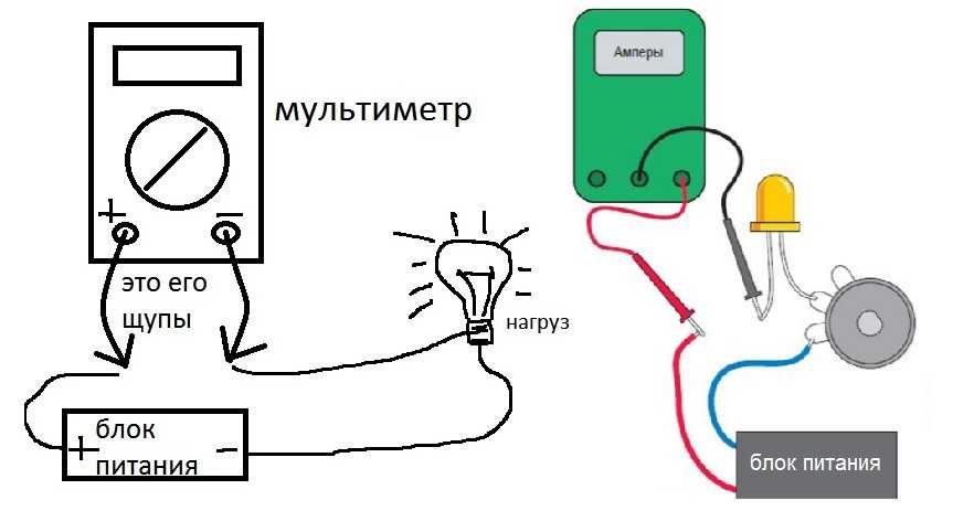
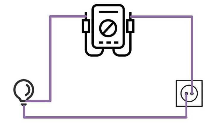
How to connect a multimeter to measure DC current
To measure the current strength, the device must be included in the open circuit. The connection diagram is given in the figure. In this case, it is important to set the red probe to the "+" of the power supply and touch the next circuit element with the black one. Do not forget when measuring that there is food, work carefully.Do not touch the bare ends of the probe or circuitry with your hands.
Alternating current
You can try the AC current measurement mode on any load connected to the household power supply and thus determine the current consumption. Since in this mode the device must be included in the circuit break, difficulties may arise with this. You can, as in the photo below, make a special cord for measurements. At one end of the cord there is a plug, on the other - a socket, cut one of the wires, attach two WAGO connectors to the ends. They are good because they also allow you to clamp the probes. After the measuring circuit is assembled, proceed to measurements.
AC current measurement with an electronic multimeter
Move the switch to the "alternating current" position, select the measurement limit. Please note that exceeding the limits can damage the instrument. In the best case, the fuse will burn out, in the worst case, the "filling" will be damaged. Therefore, we act according to the scheme proposed above: first we set the maximum limit, then we gradually reduce it. (do not forget about rearranging the probes in the sockets).
AC current measurement circuit
Everything is now ready. First, connect the load to the outlet. You can use a table lamp. We insert the plug into the network. Numbers appear on the screen. This will be the current consumed by the lamp. In the same way, you can measure the current consumption for any device.
Measuring voltage
The voltage can also be alternating or constant, respectively, we select the required position. The approach to choosing a range is the same here: if you don't know what to expect, set the maximum, gradually switching to a smaller scale. Do not forget to check if the probes are correctly connected to the right sockets.
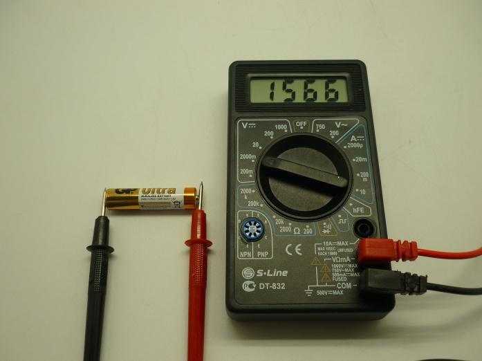
In this case, the measuring device is connected in parallel. For example, you can measure the voltage of a battery or a conventional battery. We set the switch to the position of the DC voltage measurement mode, since we know the expected value, select the appropriate scale. Next, with the probes, touch the battery on both sides. The numbers on the screen will be the voltage that this battery produces.
How to use a multimeter to measure voltage
How to use a multimeter to measure AC voltage? Yes, exactly the same. Just choose the right measurement limit.
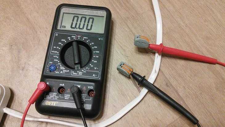
Continuity of wires with a multimeter
This operation allows you to check the integrity of the wires. On the scale, we find a dialing sign - a schematic image of the sound (look at the photo, but there is a double mode, or maybe only a dialing sign). This image was chosen because if the wire is intact, the device emits a sound.
Continuity mode on the multimeter scale
We put the switch in the desired position, the probes are connected as usual - in the lower and middle jacks. We touch one probe to one edge of the conductor, the other to the other. If we hear a sound, the wire is intact. In general, as you can see, using a multimeter is not difficult. Everything is easy to remember.


Great article! THANKS !!!
well written
+++ handsome author
Thanks, the article helped me figure it out.