How to connect a magnetic starter
Contactors or magnetic starters are used to supply power to motors or any other device. Devices designed for frequent power on and off. The connection diagram of the magnetic starter for single-phase and three-phase networks will be discussed further.
The content of the article
Contactors and starters - what's the difference
Both contactors and starters are designed to close / open contacts in electrical circuits, usually power. Both devices are assembled on the basis of an electromagnet; they can operate in DC and AC circuits of different power - from 10 V to 440 V DC and up to 600 V AC. Have:
- a certain number of working (power) contacts through which voltage is supplied to the connected load;
- a certain number of auxiliary contacts - for organizing signal circuits.
So what's the difference? What is the difference between contactors and starters. First of all, they differ in the degree of protection. The contactors are equipped with powerful interrupters. This leads to two other differences: due to the presence of arcing devices, the contactors are large and heavy, and are also used in circuits with high currents. For low currents - up to 10 A - starters are produced exclusively. By the way, they are not produced for high currents.
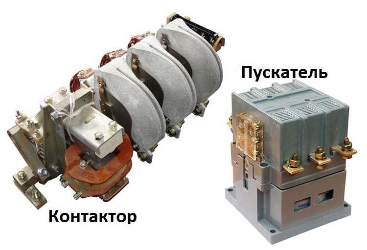
Appearance is not always so different, but it also happens
There is one more design feature: the starters are produced in a plastic case, only contact pads are brought out. Contactors, in most cases, do not have a case, therefore they must be installed in protective cases or boxes that protect against accidental contact with live parts, as well as from rain and dust.
In addition, there is some difference in the purpose. Starters are designed to start asynchronous three-phase motors. Therefore, they have three pairs of power contacts - for connecting three phases, and one auxiliary, through which power continues to flow for the engine to operate after the "start" button is released. But since such an operation algorithm is suitable for many devices, a wide variety of devices are connected through them - lighting circuits, various devices and devices.
Apparently because the "filling" and functions of both devices are almost the same, in many price lists the starters are called "small contactors".
Device and principle of operation
To better understand the connection diagrams of the magnetic starter, you need to understand its structure and principle of operation.
The basis of the starter is a magnetic circuit and an inductor. The magnetic circuit consists of two parts - movable and fixed. They are made in the form of letters "Ш" set "feet" to each other.
The lower part is fixed to the body and is stationary, the upper part is spring-loaded and can move freely. A coil is installed in the slot in the lower part of the magnetic circuit. Depending on how the coil is wound, the rating of the contactor changes. There are coils for 12 V, 24 V, 110 V, 220 V and 380 V. On the upper part of the magnetic circuit there are two groups of contacts - movable and fixed.
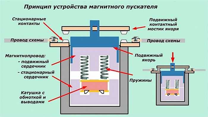
Magnetic starter device
In the absence of power, the springs squeeze out the upper part of the magnetic circuit, the contacts are in their original state. When a voltage appears (press the start button, for example) the coil generates an electromagnetic field that attracts the upper part of the core. In this case, the contacts change their position (in the photo, the picture on the right).
When the voltage fails, the electromagnetic field also disappears, the springs squeeze the moving part of the magnetic circuit up, the contacts return to their original state. This is the principle of operation of the electromagnetic starter: when the voltage is applied, the contacts close, when they fail, they open. Any voltage can be applied to and connected to the contacts - at least constant, at least variable. It is important that its parameters are not more than those declared by the manufacturer.
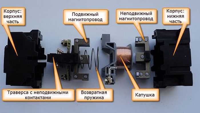
It looks like an exploded view
There is one more nuance: the starter contacts can be of two types: normally closed and normally open. Their operating principle follows from the names. Normally closed contacts are disconnected when triggered, normally open contacts are closed. The second type is used to supply power, and it is the most common.
Connection diagrams of a magnetic starter with a 220 V coil
Before moving on to the diagrams, let's figure out what and how you can connect these devices. Most often, two buttons are required - "start" and "stop". They can be made in separate bodies, or there can be a single body. This is the so-called push-button post.
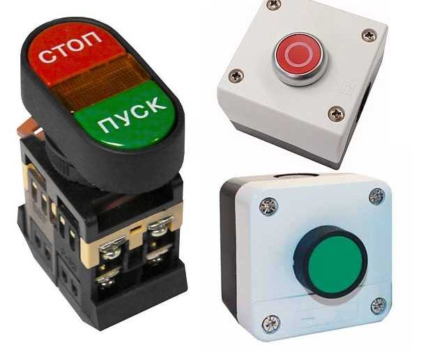
Buttons can be in the same body or in different
With separate buttons, everything is clear - they have two contacts. One is supplied with power, from the second it leaves. There are two groups of contacts in the post - two for each button: two for start, two for stop, each group on its side. There is also usually a grounding terminal. Nothing complicated either.
Connecting a starter with a 220 V coil to the network
Actually, there are many options for connecting contactors, we will describe a few. The diagram for connecting a magnetic starter to a single-phase network is simpler, so let's start with it - it will be easier to figure it out further.
Power, in this case 220 V, is fed to the coil terminals, which are designated A1 and A2. Both of these contacts are located on the top of the case (see photo).
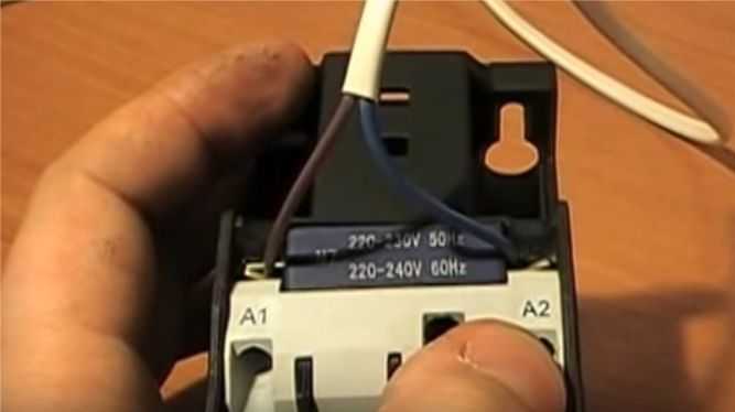
The coil can be powered here
If you connect a cord with a plug to these pins (as in the photo), the device will be in operation after the plug is inserted into the outlet. At the same time, any voltage can be applied to the power contacts L1, L2, L3, and it can be removed when the starter is triggered from contacts T1, T2 and T3, respectively. For example, the inputs L1 and L2 can be supplied with a constant voltage from the battery, which will power some device, which will need to be connected to the outputs T1 and T2.
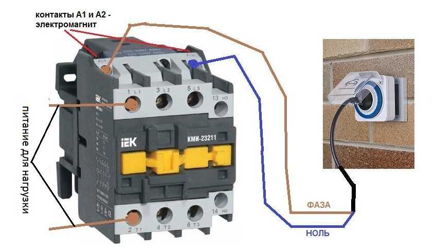
Connecting a contactor with a 220 V coil
When connecting a single-phase power supply to the coil, it does not matter to which pin to apply zero, and to which phase. You can throw the wires. Even most often, a phase is fed to A2, since for convenience this contact is also brought out on the lower side of the case. And in some cases it is more convenient to use it, and connect "zero" to A1.
But, as you understand, such a scheme for connecting a magnetic starter is not particularly convenient - you can directly feed the conductors from the power source by building in a conventional switch. But there are much more interesting options. For example, you can supply power to the coil through a time relay or a light sensor, and connect the power line to the contacts street lighting... In this case, the phase is connected to the L1 contact, and zero can be taken by connecting to the corresponding coil output connector (in the photo above it is A2).
Scheme with buttons "start" and "stop"
Magnetic starters are most often used to turn on the electric motor. It is more convenient to work in this mode if there are buttons "start" and "stop". They are connected in series to the phase supply circuit at the output of the magnetic coil. In this case, the circuit looks like the figure below. note that
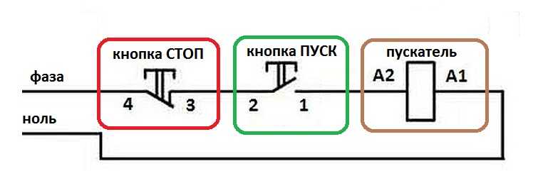
Scheme for switching on a magnetic starter with buttons
But with this method of switching on, the starter will be in operation only as long as the "start" button is held, and this is not what is required for long-term operation of the engine. Therefore, a so-called self-picking chain is added to the circuit.It is implemented using auxiliary contacts on the NO 13 and NO 14 starter, which are connected in parallel with the start button.
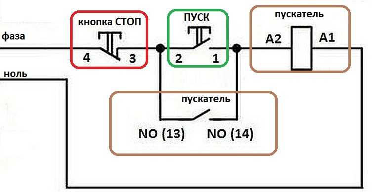
Connection diagram of a magnetic starter with a 220 V coil and a self-pickup circuit
In this case, after the START button returns to its original state, power continues to flow through these closed contacts, since the magnet is already attracted. And the power is supplied until the circuit is broken by pressing the "stop" button or triggering the thermal relay, if there is one in the circuit.
Power for the motor or any other load (phase from 220 V) is supplied to any of the contacts marked with the letter L, and is removed from the contact located under it with the marking T.
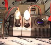
It is shown in detail in which sequence it is better to connect the wires in the following video. The only difference is that not two separate buttons are used, but a button post or a button station. Instead of a voltmeter, it will be possible to connect an engine, a pump, lighting, any device that operates on a 220 V.
Connecting a 380 V asynchronous motor through a starter with a 220 V coil
This circuit differs only in that three phases are connected to the contacts L1, L2, L3 in it and also three phases go to the load. One of the phases is connected to the starter coil - contacts A1 or A2. In the figure, this is phase B, but most often it is phase C as less loaded. The second contact is connected to the neutral wire. A jumper is also installed to keep the coil energized after releasing the START button.
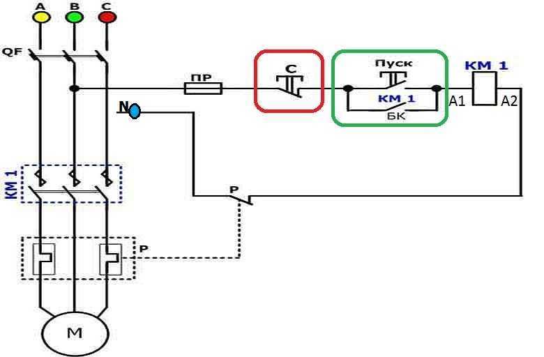
Wiring diagram for a three-phase motor through a 220 V starter
As you can see, the scheme has not changed much. Only in it a thermal relay was added, which will protect the engine from overheating. The assembly order is in the next video. Only the assembly of the contact group differs - all three phases are connected.
Reversible circuit for connecting the electric motor through starters
In some cases, it is necessary to ensure that the motor rotates in both directions. For example, for winch operation, in some other cases. The change in the direction of rotation occurs due to phase reversal - when connecting one of the starters, two phases must be reversed (for example, phases B and C). The circuit consists of two identical starters and a button block, which includes a common Stop button and two Back and Forward buttons.
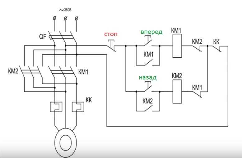
Reversible connection diagram for a three-phase motor through magnetic starters
To increase safety, a thermal relay has been added, through which two phases pass, the third is supplied directly, since protection for two is more than enough.
Starters can be with a 380 V or 220 V coil (indicated in the characteristics on the cover). If it is 220 V, one of the phases (any) is supplied to the contacts of the coil, and “zero” is supplied to the second from the shield. If the coil is 380 V, any two phases are fed to it.
Also note that the wire from the power button (right or left) is not fed directly to the coil, but through the permanently closed contacts of another starter. Contacts KM1 and KM2 are shown next to the starter coil. Thus, an electrical interlock is realized, which prevents the simultaneous supply of power to two contactors.
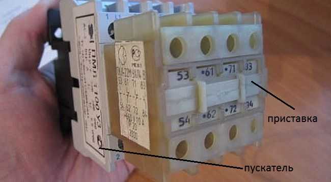
Magnetic starter with a contact attachment installed on it
Since normally closed contacts are not present in all starters, you can take them by installing an additional block with contacts, which is also called a contact attachment. This attachment snaps into special holders, its contact groups work together with the groups of the main body.
The following video shows a diagram of connecting a magnetic starter with a reverse on an old stand using old equipment, but the general procedure is clear.


there is an error on the connection diagram through the 220 V coil.
In what?
The fact that there is actually shown a circuit with a 380 volt coil - phase-phase control. With a 220 volt coil, there must be a phase-zero.
The article is good.
Only correct the mistakes that are pointed out to you.
Connecting a 380 V asynchronous motor through a starter with a 220 V coil
So far, the 220 V coil is powered through two phases (380 V).
Fixed. Thank you.