How to connect a differential machine
You can solve the problem of protecting wiring from overloads and leakage currents using a pair of devices - a circuit breaker and an RCD. But the same problem is solved by a differential circuit breaker, which combines both of these devices in one housing. The correct connection of the difavtomat and its choice will be discussed further.
The content of the article
- 1 Purpose, technical characteristics and selection
- 1.1 Characteristics and selection
- 1.1.1 Rated current
- 1.1.2 Time-current characteristic or type of electromagnetic release
- 1.1.3 Rated voltage and mains frequency
- 1.1.4 Rated breaking residual current or leakage current (settings)
- 1.1.5 Differential protection class
- 1.1.6 Rated breaking capacity
- 1.1.7 Current limiting class
- 1.1.8 Temperature mode of use
- 1.1.9 The presence of markers about the cause of the trigger
- 1.1.10 Design type
- 1.2 Manufacturer and price
- 1.1 Characteristics and selection
- 2 How to connect difavtomat
- 3 Scheme
- 4 Basic errors in connecting difavtomats
Purpose, technical characteristics and selection
Difautomat or differential circuit breaker combines functions circuit breaker and RCD. That is, this one device protects the wiring from overloads, short circuits and leakage currents. The leakage current is formed when the insulation is faulty or when touching live elements, that is, it still protects a person from electric shock.
Difautomats are installed in electrical distribution boards, most often on din-rail. They are installed instead of the automatic + RCD bundle, physically take up a little less space. To what extent depends on the manufacturer and the type of performance. And this is their main plus, which can be in demand when upgrading the network, when space in the dashboard is limited, and it is necessary to connect a number of new lines.
Difautomats serve to protect wiring from increased loads and a person from electric shock
The second positive point is cost savings. As a rule, a difavtomat costs less than a pair of automatic machines + RCDs with similar characteristics. Another positive point - it is necessary to determine only the rating of the circuit breaker, and the RCD is built in by default with the required characteristics.
There are also disadvantages: if one of the parts of the difavtomat fails, the entire device will have to be changed, and this is more expensive. Also, not all models are equipped with flags by which you can determine why the device has triggered - due to overload or leakage current - which is fundamentally important when finding out the reasons.
Characteristics and selection
Since the difavtomat combines two devices, it has the characteristics of both of them, and when choosing, everything must be taken into account. Let's figure out what these characteristics mean and how to choose a differential machine.
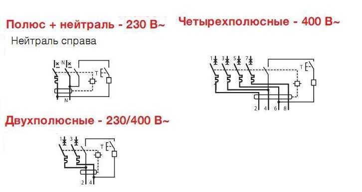
Designation of difavtomats on the diagrams
Rated current
This is the maximum current that the machine can withstand for a long time without loss of performance. It is usually indicated on the front panel. Rated currents are standardized and can be 6 A, 10 A, 16 A, 20 A, 25 A, 32 A, 40 A, 50 A, 63A.
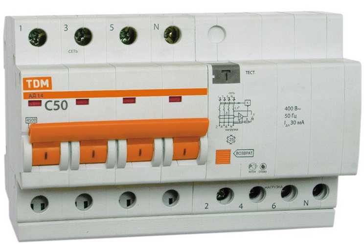
Four-pole difavtomat for connection to a 380 V network
Small ratings - 10 A and 16 A - are placed on the lighting line, medium ones - on powerful consumers and outlet groups, and powerful ones - 40 A and above - are mainly used as an introductory (general) difavtomat. It is selected depending on the cross-section of the cable, just like with choosing the rating of the circuit breaker.
Time-current characteristic or type of electromagnetic release
It is displayed next to the rating, denoted by the Latin letters B, C, D. Indicates at what overloads relative to the rating the machine is disconnected (to ignore short-term starting currents).
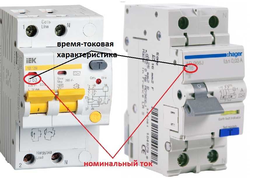
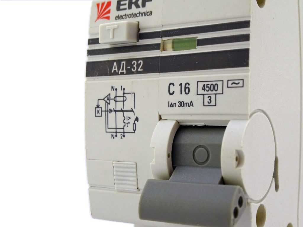
The nominal value of the difavtomat and its time-current characteristic
Category B - if the current is exceeded by 3-5 times, C - if the rating is exceeded by 5-10 times, type D is disconnected at loads that exceed the rating by 10-20 times. In apartments, type C difavtomats are usually installed, in rural areas, B can be installed, in enterprises with powerful equipment and large starting currents - D.
Rated voltage and mains frequency
For which networks the device is intended - 220 V and 380 V, with a frequency of 50 Hz. There are no others in our retail network, but it's worth checking anyway.
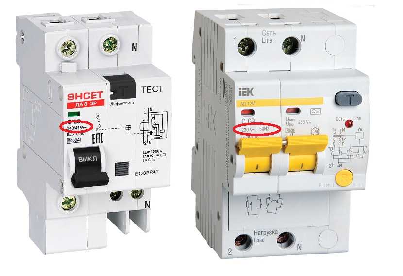
Voltage and frequency for which the differential circuit breaker is designed
Differential machines can be double-labeled - 230/400 V. This suggests that this device can operate in both 220 V and 380 V networks. In three-phase networks, such devices are installed on outlet groups or on individual consumers, where used only one of the phases.
As water difavtomats for three-phase networks, devices with four inputs are required, and they differ significantly in size. It is impossible to confuse them.
Rated breaking residual current or leakage current (settings)
Displays the sensitivity of the device to the generated leakage currents and shows under what conditions the protection will trip. In everyday life, only two ratings are used: 10 mA for installation on a line, in which only one powerful device or consumer is installed, in which two dangerous factors are combined - electricity and water (flowing or storage electric water heater, hob, oven,Dishwasher etc.).
For lines with a group of outlets and outdoor lighting, they install difavtomats with a leakage current of 30 mA, they are not usually installed on the lighting line inside the house - to save money.
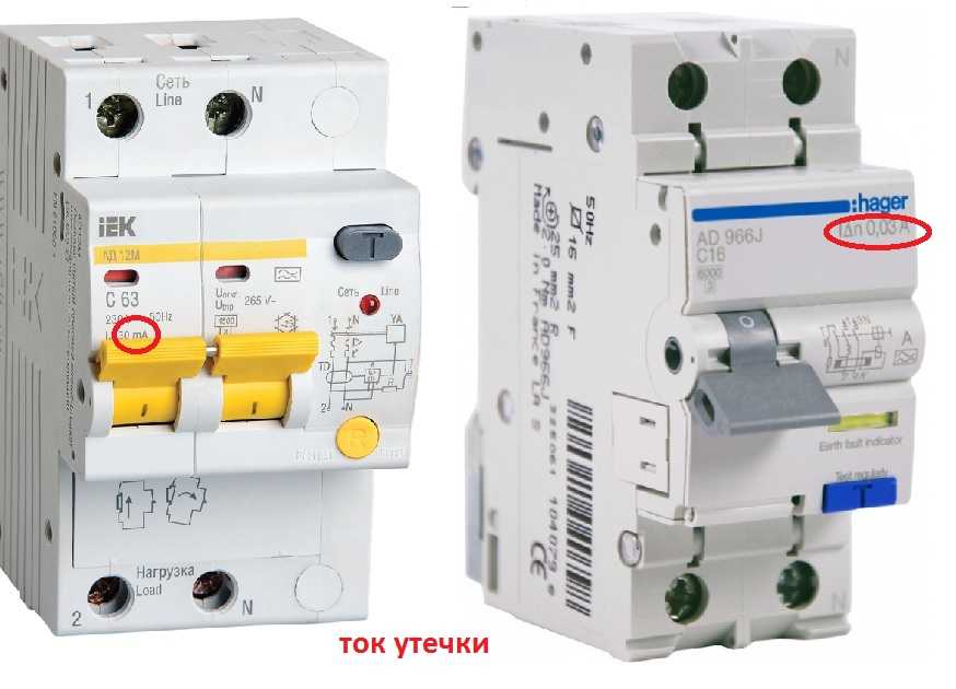
Leakage current or settings on the differential machine
A simple value in milliamperes can be written on the device (as in the photo on the left) or an alphabetic designation of the setting current (in the photo on the right) can be applied, after which there are numbers in amperes (at 10 mA it costs 0.01 A, at 30 mA the number 0 , 03 A).
Differential protection class
Shows what type of leakage currents this device protects. There are letter and graphic images. Usually they put an icon, but there may be a letter (see the table).
| Letter designation | Graphic designation | Decoding | Application area |
|---|---|---|---|
| AS |  | Reacts to AC sinusoidal current | They are placed on a line to which simple equipment is connected without electronic control |
| A |  | Reacts to sinusoidal alternating current and pulsating direct current | It is used on the lines from which the equipment with electronic control is powered |
| IN |  | Captures variable, pulse, constant and smoothed constant. | Mainly used in production with a wide variety of equipment |
| S | With shutdown time delay 200-300 ms | In complex circuits | |
| G | With shutdown time delay 60-80 ms | In complex circuits |
The choice of the differential protection class of the difavtomat is based on the type of load. If this is a technique with microprocessors, class A is required, class AC is suitable for lighting or power-on lines of simple devices. Class B is rarely set in private houses and apartments - there is no need to "catch" all types of leakage currents. Connecting a difavtomat of class S and G makes sense in multi-level protection schemes. They are put as input if there are other differential trip devices in the circuit further. In this case, when one of the downstream leakages is triggered, the input will not turn off and the serviceable lines will be in operation.
Rated breaking capacity
Shows what current the difavtomat is able to turn off in the event of a short circuit and remain operational. There are several standard ratings: 3000 A, 4500 A, 6000 A, 10,000 A.
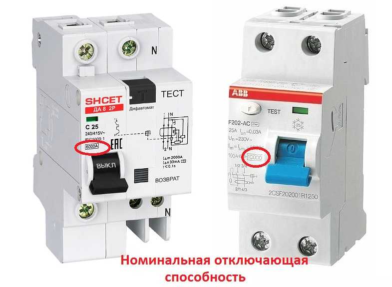
Breaking capacity of difavtomat
The choice of a difavtomat for this parameter depends on the type of network and on the range of the substation. In apartments and houses at a sufficient distance from the substation, difavtomats with a breaking capacity of 6,000 A are used, close to substations they are set at 10,000 A. In rural areas, when power is supplied by air and in networks that have not been modernized for a long time, 4,500 A.
On the case, this number is indicated in a square frame. The location of the inscription can be different - it depends on the manufacturer.
Current limiting class
It takes some time for the short-circuit current to reach its maximum value. The sooner the power supply is disconnected from the damaged line, the less chance of damage. The current limiting class is displayed in numbers from 1 to 3. The third class - disconnects the line the fastest. So the choice of a difavtomat on this basis is simple - it is advisable to use devices of the third class, but they are expensive, but they remain operational longer. So, if you have the financial ability, install difavtomats of this class.
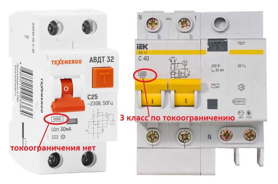
Current limiting difavtomat
This characteristic is shown on the case in a small square frame next to the rated breaking capacity. It can be on the right (for Legranda) or below (for most other manufacturers). If you did not find such a mark either on the case or in the passport, then this machine has no current limitation.
Temperature mode of use
Most differential circuit breakers are designed for indoor use. They can operate at temperatures from -5 ° C to + 35 ° C. In this case, nothing is placed on the case.
Designation of increased frost resistance of difavtomat
Sometimes the shields are outside and conventional protective devices will not work. For such cases, difavtomats are produced with a wider temperature range - from -25 ° C to + 40 ° C. In this case, a special sign is placed on the case, which looks a bit like an asterisk.
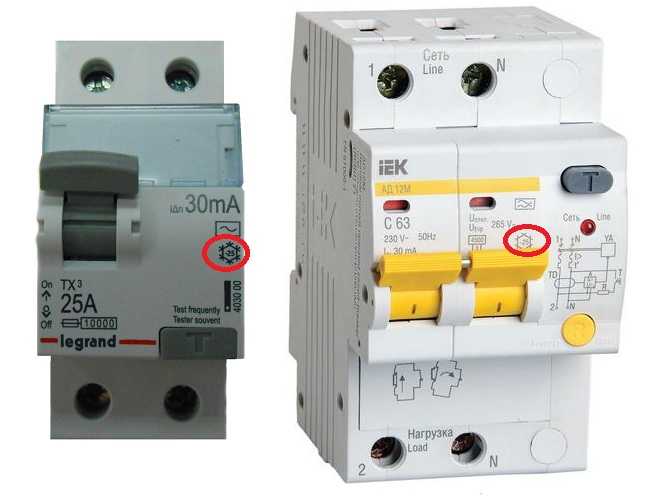
The presence of markers about the cause of the trigger
Not all electricians like to install differential automatons, as they believe that the circuit breaker + RCD is more reliable. The second reason is that if the device works, it is impossible to determine what caused this - an overload, and you just need to turn off some device, or a leakage current, and you need to look for where and what happened.
To solve at least the second problem, manufacturers began to make flags that show the reason for the operation of the difavtomat. In some models, this is a small platform, according to the position of which the reason for the shutdown is determined.
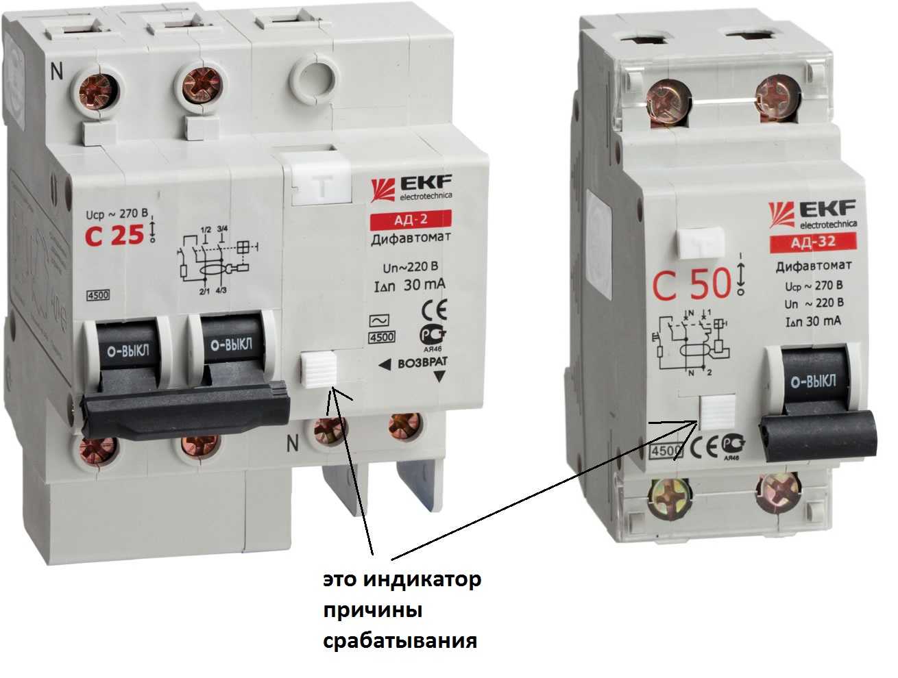
A checkbox that shows the reason for the shutdown
If the shutdown was caused by an overload, the indicator remains flush with the case, as in the photo on the right. If the difavtomat triggered in the presence of a leakage current, the flag protrudes a certain distance from the body.
Design type
There are two types of differential automatic machines: electromechanical or electronic. Electromechanical ones are more reliable, since they remain operational even in the event of a power failure. That is, if a phase is lost, they will be able to work and turn off zero as well. Electronic ones require power to work, which is taken from the phase wire and, if the phase is lost, they lose their performance.
Manufacturer and price
It is not worth saving in electricity, especially on devices that protect wiring and life. Therefore, it is recommended to always buy components from well-known manufacturers. Legrand (Legrand) and Schneider (Schneider), Hager (Hager) are the leaders in the market, but their products are expensive, and there are many fakes. IEK (IEK), ABB (ABB) have not so high prices, but there are more problems with nm. In this case, it is better not to contact unknown manufacturers, since they are often simply inoperable.
The choice is actually not that small and even if you limit yourself to just these five firms. Each manufacturer has several lines that differ in price, and significantly.To understand the difference, you need to carefully look at the specifications. Each of them influences the price, so carefully study all the data before buying.
How to connect difavtomat
Let's start with the installation methods and the order of connecting the conductors. Everything is very simple, there are no special difficulties. In most cases, it is mounted on a dinrake. For this, there are special tabs that hold the device in place.
Dinrake mount
Electrical connection
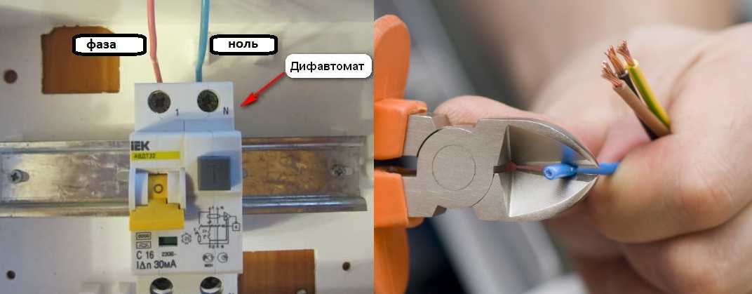
The difavtomat is connected to the mains with wires in isolation. The section is selected based on the nominal value. Usually the line (power supply) is connected to the upper sockets - they are signed with odd numbers, the load - in the lower ones - are signed with even numbers. Since both phase and zero are connected to the differential automaton, so as not to confuse, the sockets for "zero" are signed with the Latin letter N.
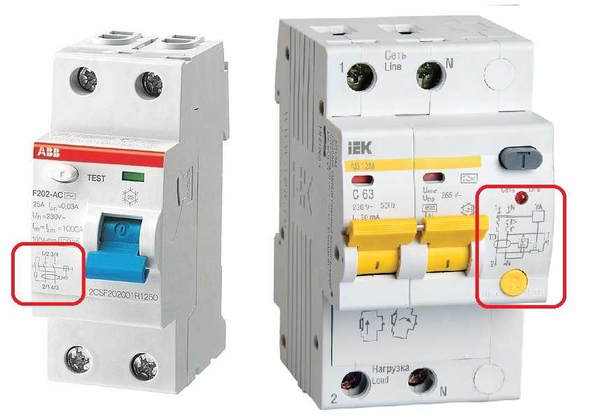
The connection diagram of the difavtomat is usually on the case
In some lines, you can connect the line to both the upper and lower jacks. An example of such a device is shown in the photo above (left). In this case, numbering is written on the diagram through a fraction - 1/2 at the top and 2/1 at the bottom, 3/4 at the top and 4/3 at the bottom. This means that it does not matter whether the line is connected from above or below.
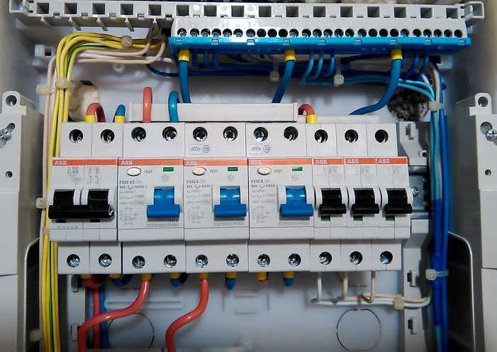
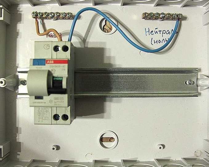
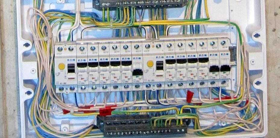
Connecting a difavtomat on the switchboard
Before connecting the line, the insulation is removed from the wires at a distance of about 8-10 mm from the edge. At the desired terminal, slightly loosen the fixing screw, insert the conductor, tighten the screw with a sufficiently large effort. Then the wire is tugged several times to make sure the contact is normal.
Functional check
After you have connected the difavtomat, applied power, you need to check the system's performance and correct installation. First, we test the unit itself. For this, there is a special button labeled "Test" or just the letter T. After the switches have been put into working state, we press this button. In this case, the device must "knock out". This button artificially creates a leakage current, so we checked the operation of the difavtomat. If there was no response, you need to check the correct connection, if everything is correct, the device is faulty
If the difavtomat triggered when pressing the "T" button, it is operational
Further testing is connecting a simple load to each outlet. This will check the correct wiring of the outlet groups. And the last one is the alternating switching on of household appliances, to which separate power lines are connected.
Scheme
When developing a wiring diagram in an apartment or house, there can be many options. They can differ in the convenience and reliability of operation, the degree of protection. There are simple options that require a minimum of cost. They are usually implemented in small networks. For example, in dachas, in small apartments with a small amount of household appliances. In most cases, you have to install a large number of devices that ensure the safety of the wiring and protect people from electric shock.
Schemes come in different levels of complexity
Simple circuit
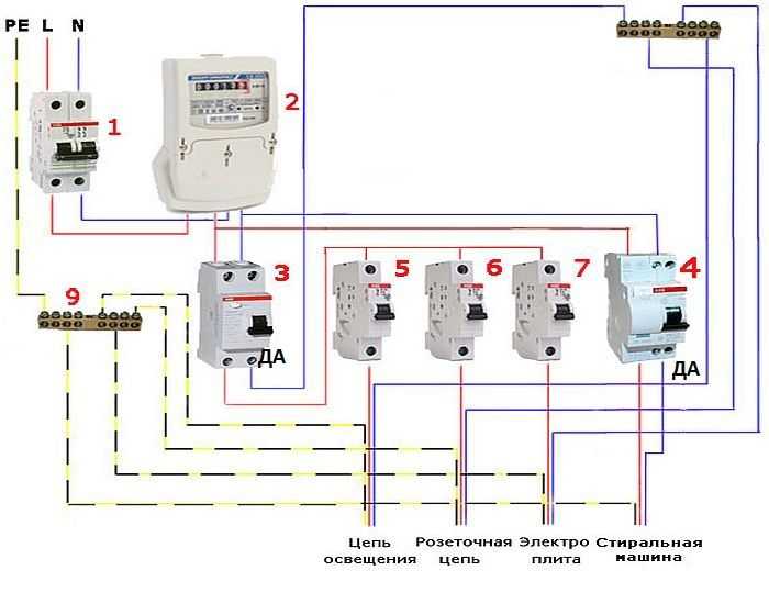
It does not always make sense to install a large number of protective devices. For example, at a seasonal dacha, where there are only a few sockets and lighting, it is enough to put only one difavtomat at the entrance, from which separate lines will go to groups of consumers - sockets and lighting - through the machines.
A simple diagram for connecting a difavtomat to a small network
This circuit will not require large costs, but when a leakage current appears on any of the lines, the difavtomat will work, de-energizing everything. There will be no light until the causes are clarified and eliminated.
Better protection
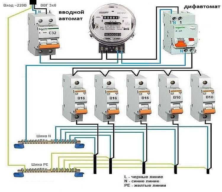
As already mentioned, some difavtomats are put on "wet" groups. These include the kitchen, bathroom, outdoor lighting, and appliances that use water (except for the washing machine).This method of building the system provides a higher degree of security and better protects wiring, equipment and people.
More complex and reliable scheme: connecting a difavtomat to each potentially dangerous device
The implementation of this method of wiring will require large material costs, but the system will work more reliably and stably. Since when one of the protective devices is triggered, the rest will remain operational. This connection of a difavtomat is used in most apartments and in small houses.
Selective schemes
In branched power supply networks, it becomes necessary to make the system even more complex and expensive. In this version, after the counter, an input differential automaton of class S or G is installed. Further, each group has its own automaton, and if necessary, they are also installed on separate consumers. For connecting a difavtomat for this case, see the photo below.
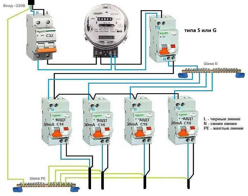
Selective scheme for installing difavtomat
With this design of the system, when one of the linear devices is triggered, all the others will remain in operation, since the input differential switch has a response delay.
Basic errors in connecting difavtomats
Sometimes after connecting the difavtomat, it does not turn on or is cut down when connecting any load. This means that something was done wrong. There are several common mistakes that occur when self-assembly of the shield:
- The protective zero (ground) and working zero (neutral) wires are combined somewhere. With such an error, the difavtomat does not turn on at all - the levers are not fixed in the upper position. We'll have to look for where "ground" and "zero" are combined or mixed up.
- Sometimes, when connecting a difavtomat, zero to the load or to the machines located below is taken not from the output of the device, but directly from the zero bus. In this case, the circuit breakers are in the working position, but when you try to connect the load, they instantly turn off.
- From the output of the difavtomat, zero is not fed to the load, but goes back to the bus. The zero for the load is also taken from the bus. In this case, the circuit breakers are in the working position, but the "Test" button does not work and when you try to turn on the load, a shutdown occurs.
- Zero connection is messed up. From the zero bus, the wire must go to the corresponding input, indicated by the letter N, which is at the top, not down. From the lower zero terminal, the wire must go to the load. Symptoms are similar: the breakers are turned on, the "Test" does not work, when the load is connected, it is triggered.
- If there are two difavtomats in the circuit, the neutral wires are mixed up. With such an error, both devices turn on, "Test" works on both devices, but when any load is turned on, it knocks out both machines at once.
- In the presence of two difavtomats, the zeros coming from them were connected somewhere further. In this case, both machines are cocked, but when you press the "test" button of one of them, two devices are cut down at once. A similar situation occurs when any load is turned on.
Now you can not only choose and connect a differential circuit breaker, but also understand why it knocks out, what exactly went wrong and fix the situation yourself.