How to connect and adjust the water pressure switch
When organizing a water supply system at home, not only a pump is needed, but also automation to ensure its operation. One necessary instrument is a water pressure switch. This small device turns on the pump when the pressure in the system drops and turns it off when the threshold is reached. The value of the on and off parameters can be adjusted. How this device works, how to connect it and how to regulate it - in the article.
The content of the article
Purpose and device
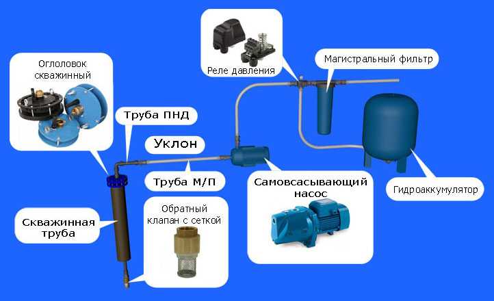
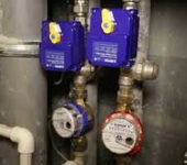
In order to maintain a constant pressure in the water supply system of a private house, two devices are needed - a hydraulic accumulator and a pressure switch. Both of these devices are connected via a pipeline to the pump - the pressure switch is located in the middle between the pump and the accumulator. Most often it is located in the immediate vicinity of this tank, but some models can be installed on the pump body (even submersible). Let's take a look at the purpose of these devices and how the system works.
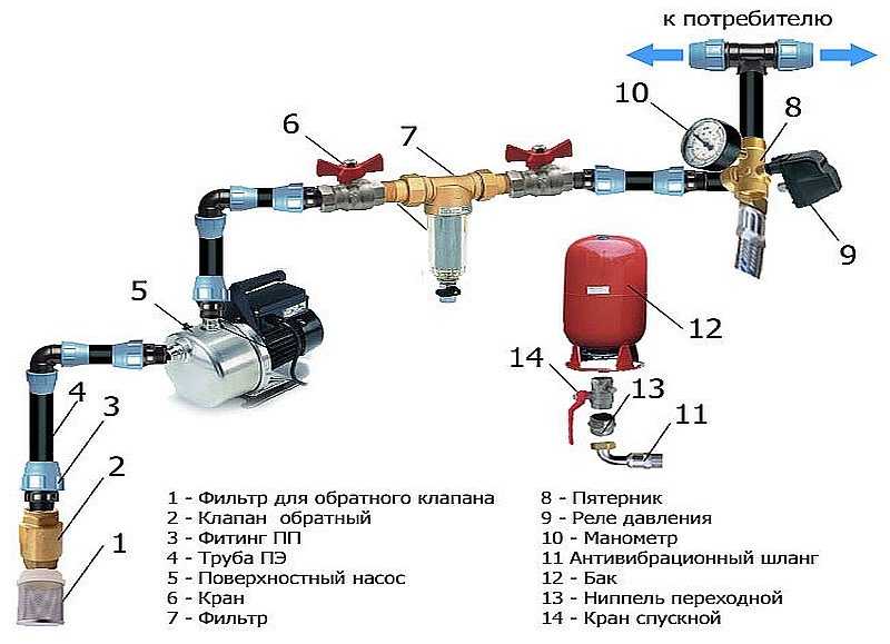
One of the pump connection diagrams
A hydraulic accumulator is a container divided into two halves by an elastic bulb or membrane. In one there is air under some pressure, in the second water is pumped. The water pressure in the accumulator and the amount of water that can be pumped there is regulated by the amount of pumped air. The more air there is, the higher the pressure is maintained in the system. But at the same time, less water can be pumped into the tank. Usually it is possible to pump no more than half of the volume into the container. That is, it will be possible to pump no more than 40-50 liters into a 100-liter hydroaccumulator.
For normal operation of household appliances, a range of 1.4 atm - 2.8 atm is required. To maintain such a framework, a pressure switch is required. It has two operating limits - upper and lower. When the lower limit is reached, the relay starts the pump, it pumps water into the accumulator, and the pressure rises in it (and in the system). When the pressure in the system reaches the upper limit, the relay turns off the pump.
In a circuit with a hydraulic accumulator, water is consumed from the tank for some time. When enough has flowed out for the pressure to drop to the lower response threshold, the pump will start. This is how this system works.
Pressure switch device
This device consists of two parts - electrical and hydraulic. The electrical part is a group of contacts that closes and opens by turning the pump on / off. The hydraulic part is a diaphragm that exerts pressure on the metal base and springs (large and small) with which the pump on / off pressure can be changed.

Water pressure switch device
The hydraulic outlet is located on the back of the relay. It can be an outlet with an external thread or with an American-style nut. The second option is more convenient when installing - in the first case, you either need to look for an adapter with a union nut of a suitable size or twist the device itself, screwing it onto the thread, and this is not always possible.
The inputs of the electrical part are also located on the back of the case, and the terminal block itself, where the wires are connected, is hidden under the cover.
Types and varieties
Water pressure switches are of two types: mechanical and electronic. Mechanical ones are much cheaper and are usually preferred, while electronic ones are mainly brought on order.
| Name | Pressure regulation limit | Factory settings | Manufacturer / country | Device protection class | Price |
|---|---|---|---|---|---|
| RDM-5 Jileks | 1- 4.6 atm | 1.4 - 2.8 atm | Jileks / Russia | IP 44 | 13-15$ |
| Italtecnica PM / 5G (m) 1/4 " | 1 - 5 atm | 1.4 - 2.8 atm | Italy | IP 44 | 27-30$ |
| Italtecnica PT / 12 (m) | 1 - 12 atm | 5 - 7 atm | Italy | IP 44 | 27-30$ |
| Grundfos (Condor) MDR 5-5 | 1.5 - 5 atm | 2.8 - 4.1 atm | Germany | IP 54 | 55-75$ |
| Italtecnica PM53W 1 " | 1.5 - 5 atm | Italy | 7-11 $ | ||
| Genebre 3781 1/4 " | 1 - 4 atm | 0.4 - 2.8 atm | Spain | 7-13$ |
The difference in prices in different stores is more than significant. Although, as usual, when buying cheap copies, there is a risk of running into a fake.
Water pressure switch connection
The water pressure switch for the pump is connected to two systems at once: to electricity and water supply. It is installed permanently, since there is no need to move the device.
Electrical part
A dedicated line is not required to connect a pressure switch, but it is desirable - there are more chances that the device will work longer. A cable with a solid copper conductor with a cross-section of at least 2.5 square meters must go from the shield. mm. It is desirable to install a bundle machine + RCD or difavtomat. The parameters are selected according to the current and depend more on the characteristics of the pump, since the water pressure switch consumes very little current. The circuit must have grounding - the combination of water and electricity creates an area of increased danger.
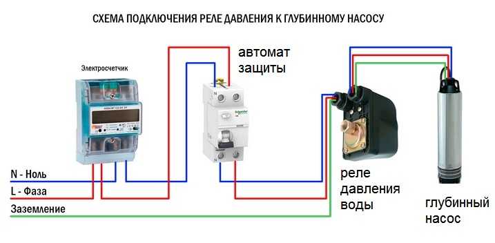
Wiring diagram for water pressure switch to switchboard
The cables are led into special glands on the back of the case. There is a terminal block under the cover. It has three pairs of contacts:
- grounding - the appropriate conductors are connected from the shield and from the pump;
- line or "line" terminals - for connecting the phase and neutral wires from the shield;
- terminals for similar wires from the pump (usually on the block located above).
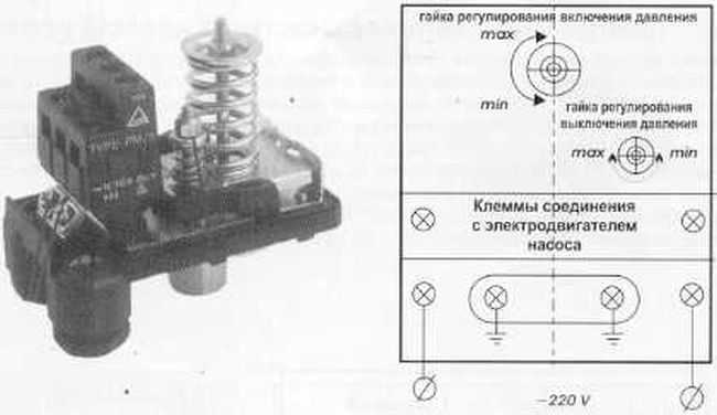
Arrangement of terminals on the body of the water pressure switch
The connection is standard - the conductors are stripped of insulation, inserted into the connector, tightened with a clamping bolt. Pulling on the conductor, check whether it is securely clamped. After 30-60 minutes the bolts can be retightened, as copper is a soft material and the contact may loosen.
Pipeline connection
There are different ways to connect a water pressure switch to a plumbing system. The most convenient option is to install a special adapter with all required outputs - a five-way fitting. The same system can be assembled from other fittings, it is just that the ready-made version is always flatter.
It is screwed onto a branch pipe on the back of the body, a hydraulic accumulator is connected to the rest of the outputs, supplying a hose from the pump and a line that goes into the house. You can also install a sump and a pressure gauge.
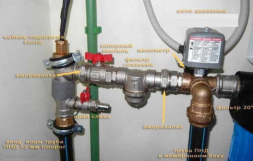
Example of piping a pressure switch for a pump
A pressure gauge is a necessary thing - to control the pressure in the system, monitor the relay settings. A sump is also a necessary device, but it can be installed separately on the pipeline from the pump. There is generally desirable a whole filter system for water purification.
With this scheme, at a high flow rate, water is supplied directly to the system - bypassing the accumulator. It starts to fill up after all the taps in the house are closed.
Water pressure switch adjustment
Consider the process of adjusting the most popular instance - RDM-5. It is produced by different factories. The limits of adjustments change, since different pressures are required in different sized water pipes. This device leaves the factory with a basic setting. Usually it is 1.4-1.5 atm - the lower threshold and 2.8-2.9 atm - the upper threshold. If you are not satisfied with some parameter, you can reconfigure it as required. Such a procedure is usually necessary when installing a jacuzzi: a standard pressure of 2.5-2.9 atm is not enough for the desired effect. In most other cases, reconfiguration is not required.
The passport has a full description
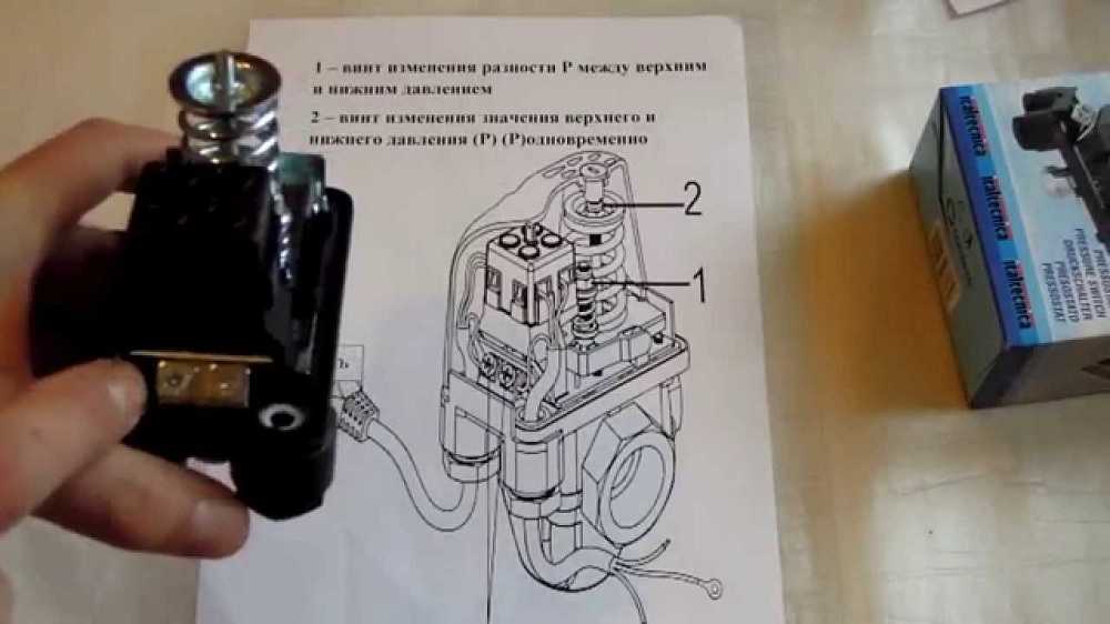
The RDM-5 water pressure switch has two springs, which regulate the pump off / on threshold. These springs differ in size and purpose:
- large adjusts the limits (upper and lower at once);
- a small one changes the delta - the gap between the upper and lower boundaries.
Parameters change occurs when tightening or unscrewing the nuts on the springs. If the nuts are tightened, the pressure increases, if they are loosened, it drops.It is not necessary to turn the nuts strongly one turn - this is a change of about 0.6-0.8 atm, and this is usually a lot.
How to determine relay thresholds
The pump activation threshold (and the lower pressure threshold on the water pressure switch) are related to the pressure in the air part of the accumulator - the minimum pressure in the system should be 0.1-0.2 atm higher. For example, if the pressure in the tank is 1.4 atm, the shutdown threshold is desirable at 1.6 atm. With these parameters, the tank membrane will last longer. But in order for the pump to work under normal conditions, look at its characteristics. He also has a lower pressure threshold. So, it should not be higher than the selected value (lower or equal). Based on these three parameters, you select the activation threshold.
By the way, the pressure in the accumulator must be checked before adjustment - there are significant deviations from the declared parameters. A nipple is hidden under a removable cover (in different models it looks and is located in different places). Through it, you can connect a pressure gauge (you can car or the one that you have) and see the actual pressure. By the way, it can be adjusted through the same nipple - increase or decrease if necessary.
Shutdown thresholds depend on system components
The upper threshold - pump shutdown - is set automatically during adjustment. In the initial state, the relay is set to some kind of differential pressure (delta). This difference is usually 1.4-1.6 atm. So if you set the switch on, for example, at 1.6 atm, the shutdown threshold will automatically be set at 3.0-3.2 atm (depending on the relay settings). If you need a higher pressure (raise water to the second floor, for example, or the system has many taps), you can increase the shutdown threshold. But there are limitations:
- The parameters of the relay itself. The upper limit is fixed and in household models usually does not exceed 4 atm. It just won't work anymore.
- The upper limit of the pump pressure. This parameter is also fixed and the pump should be turned off at least 0.2-0.4 atm before the declared characteristics. For example, the upper pressure threshold of the pump is 3.8 atm, the shutdown threshold on the water pressure switch should be no higher than 3.6 atm. But in order for the pump to work for a long time and without overloads, it is better to make a larger difference - overloads have a too bad effect on the operating time.
That's all for the choice of water pressure switch settings. In practice, when setting up the system, you have to adjust the selected parameters in one direction or the other, because you need to choose everything so that all the draw-off points work normally, including household appliances. Therefore, it is often said that the parameters are chosen by the "scientific poke" method.
Setting the water pressure switch for a pump or pumping station
Setting up your system will require a reliable pressure gauge that you can trust. It is connected to the system near the pressure switch.
The adjustment process consists of twisting two springs: large and small. If you need to raise or lower the lower threshold (turning on the pump), twist the nut on a large spring. If you turn it clockwise, the pressure rises; counter-clockwise, it falls. Turn a very small amount - half a turn or so.
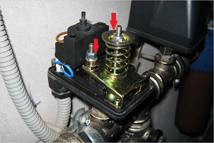
The water pressure switch is adjusted using springs
The sequence of actions is as follows:
- The system is started, the pressure gauge is monitored at what pressure the pump turned on and off.
- Press in or release the large spring.
- The parameters are turned on and checked (at what pressure it turned on, at which it turned off). Both values are shifted by the same amount.
- Make adjustments if necessary (adjust the large spring again).
- After the lower threshold is set the way you want it to be, they begin to adjust the pump shutdown threshold. To do this, a small spring is pressed or lowered. Do not twist the nut on it either - half a turn is usually enough.
- Turn on the system again and look at the results. If everything suits you, they stop there.
What else do you need to know about adjusting the water pressure switch? That not all models have the ability to change the delta, so take a closer look when buying. There is a pressure switch for the pump in a moisture- and dust-protected housing. They can be installed in a sump, some models can be installed directly on the pump housing if it has such an outlet.
In some water pressure switches there is also an idle (dry) switch, in general this device is in a separate case, but there are also combined ones. Protection against idling is necessary so that the pump does not break if suddenly there is no water in the well or well. Some pumps have built-in protection of this type, for others they buy and install the relay separately.


Good day! the membrane was replaced and the pressure was pumped up to 1.5 atm. The pump turns on at a pressure of 1.2-1.3 atm and turns off at 2.8-2.9 atm. Everywhere they write that the pressure in the membrane should be less by 0.2 atm. than the lower limit, i.e. pump start pressure. If we assume that both pressure gauges (both on the relay and in the membrane) work without errors, then can it be that the pump turns on at a pressure lower than in the membrane. As I understand this setting is incorrect, what is the threat to the equipment and what needs to be done? Adjust the pressure switch, make the lower limit 1.6 atm? Or remove the pressure to 1.1 in the membrane? Or there may be a difference in the readings of the manometers, since I measured the pressure in the car, the wheels made a maximum of 2.2 atm, and this manometer showed 2.5.
Most likely, the error of the manometer. If the sound of the station is working normally, then it is. Can you measure it with one manometer in turn?
Everything is correct. There must be more pressure in the tank (expansion tank) so that all the water comes out of it (at 1.5 atm) and the pump turns on immediately (since the water does not expand anymore). If there is less pressure in the tank, then, firstly, it will not work completely, and secondly, at low pressures, the tank will give water for a long time at a pressure of 1.3 atm, the pump will not turn on, so the water will flow ate-ate in the tap.
The preset pressure in the tank should be 0.2-0.3 atmospheres less than the pressure to turn on the pump. Otherwise, the membrane will block the water outlet (an unpleasant sound appears). So the instructions for the accumulator are written.
Good day. A well, a pump, a taxiway, a hydraulic accumulator, a regulated flow, in general, everything is like people have ...
The system worked fine for six years. This year, there was some kind of drawdown in the water supply: There is a normal pressure, after 40-50 seconds the pressure drops, for 2-3 seconds a small trickle flows, then the pressure is restored again. And so on, in a circle ... ..
Tell me, please, what is the reason? What screws to tighten? Or throw out the RD? The pressure in the accumulator is 2 atm (measured with an auto manometer).
Good afternoon!
How did you measure the pressure in the tank?
It is necessary to measure without water, i.e. disconnect the hose from the tank.
I had something similar when the membrane burst.
In this case, the system works like a rigid system, because there is no elastic force of the injected air.
You may have measured the water pressure.
Ksati, did you not pay attention to the nipple? When you connected the pressure gauge, did not splash water come out of it? This may speak in favor of a torn membrane.
Tell me, please, the relay stopped turning on the pump.The pump turns on directly, a click is heard in the relay, I turn off "" directly "and turn it on through the relay, but when the accumulator runs out of water, the relay does not turn on the pump.
The pressure switch connection hole may be clogged. Also, sometimes plaque forms under the pressure switch membrane and does not allow the stem to work normally.
Good afternoon, the system is made with the "kid" pump - 4 meters hose - check valve - pressure switch - filter - after 10 meters of the pipeline, the hydraulic accumulator - then the point of consumption. When the pressure drops, the relay turns on, the pump works, pumps up pressure, then the relay starts to turn off frequently and turn on up to ten times, then it turns off and so on every other time - it's normal, frequent on / off. I can't understand what is the reason.
Hello! What if the pressure does not gain 3 Pa? on the accumulator, can you tell me?
Three is indicated in the instructions? I average around 2.2, everything works fine.
Hello, advise. I decided to adjust the surface pump. readjust the pressure switch and check the pressure in the accumulator. It turned out there is no pressure. decided to pump up the pump could not. as if some kind of plug unscrewed the nipple the same. What to do.