How to measure with a megohmmeter
To assess the performance of the cable, wiring, it is necessary to measure the insulation resistance. For this, there is a special device - a megohmmeter. It applies a high voltage to the measured circuit, measures the current flowing through it, and outputs the results to a screen or scale. How to use a megohmmeter and we will consider in this article.
The content of the article
Device and principle of operation
Megohmmeter - a device for testing insulation resistance. There are two types of instruments - electronic and pointer. Regardless of the type, any megohmmeter consists of:
- A constant voltage source.
- Current meter.
- Digital screen or scale of measurement.
- Probes, through which the voltage from the device is transmitted to the measured object.
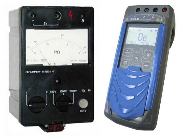
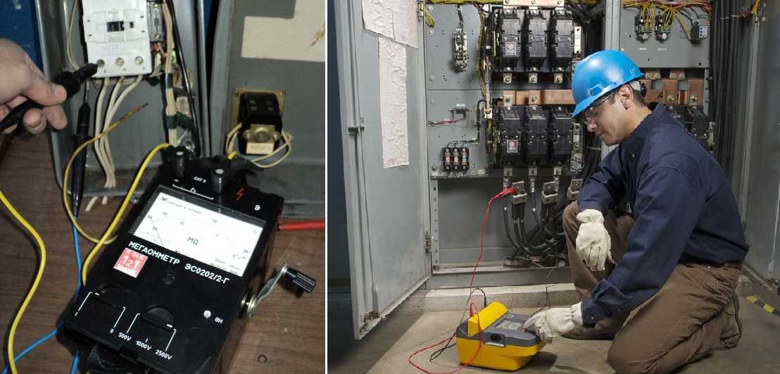
It looks like a pointer megohmmeter (left) and electronic (right)
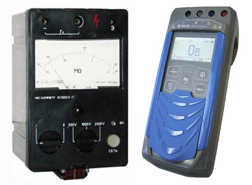
In dial gauges, the voltage is generated by a dynamo built into the case. It is driven by a meter - it turns the handle of the device with a certain frequency (2 revolutions per second). Electronic models take power from the mains, but can also operate on batteries.
The work of the megohmmeter is based on Ohm's law: I = U / R. The device measures the current that flows between two connected objects (two cable cores, core-ground, etc.). Measurements are made with a calibrated voltage, the value of which is known, knowing the current and voltage, you can find the resistance: R = U / I, which is what the device does.
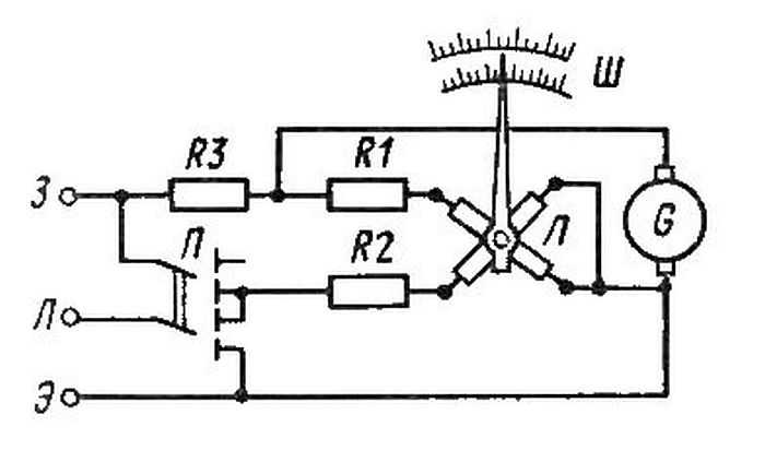
Approximate diagram of a mag-ohm meter
Before testing, the probes are installed in the corresponding sockets on the device, after which they are connected to the measured object. During testing, a high voltage is generated in the device, which is transmitted to the tested object with the help of probes. Measurement results are displayed in mega ohms (MΩ) on a scale or display.
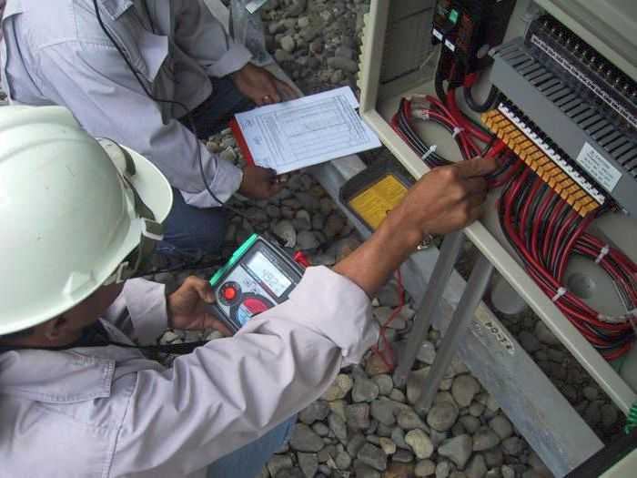
Working with a megohmmeter
During tests, the megohmmeter generates a very high voltage - 500 V, 1000 V, 2500 V. In this regard, measurements must be made very carefully. At enterprises, persons who have an electrical safety group of at least 3 are allowed to work in the device.
Before taking measurements with a megohmmeter, the circuits under test are disconnected from the power supply. If you are going to check the condition of the wiring in a house or apartment, you must turn off the switches on dashboard or unscrew the plugs. Then turn off all semiconductor devices.
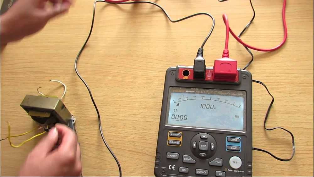
One of the options for modern megohmmeters
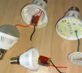
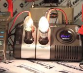
If you check the outlet groups, remove the plugs of all the devices that are included in them. If the lighting circuits are checked, the bulbs are unscrewed. They will not withstand the test voltage. When checking the insulation of the motors, they are also completely disconnected from the power supply. After that, ground is connected to the tested circuits. For this, a stranded wire in a sheath with a cross section of at least 1.5 mm2 is attached to the "earth" bus. This is the so-called portable grounding. For safer operation, the free end with the bare conductor is attached to a dry wooden grip. But the bare end of the wire must be accessible so that it can touch the wires and cables.
Requirements for ensuring safe working conditions
Even if you want to measure the insulation resistance of a cable at home, before using a megohmmeter, you should familiarize yourself with the safety requirements. There are several basic rules:
- Only hold the test leads at the insulated part bounded by stops.
- Before connecting the device, disconnect the voltage, make sure that there are no people nearby (along the entire measured route, if we are talking about cables).

How to use a megohmmeter: electrical safety rules
- Before connecting the probes, remove the residual voltage by connecting a portable ground. And disconnect it after the probes are installed.
- After each measurement, remove the residual voltage from the probes by connecting their bare parts together.
- After the measurement, connect a portable ground to the measured core, removing the residual charge.
- Work with gloves.
The rules are not very complicated, but your safety depends on their implementation.
How to connect probes
The device usually has three sockets for connecting probes. They are located at the top of the instruments and are labeled:
- E - screen;
- L - line;
- З - earth;
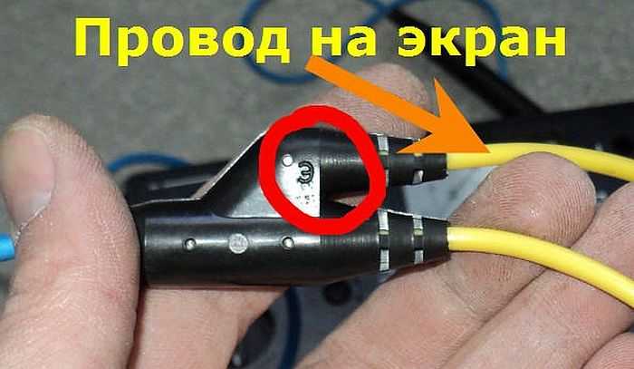
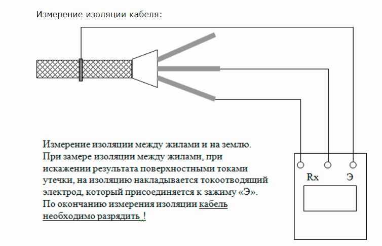
There are also three styli, one of which has two tips on one side. It is used when it is necessary to eliminate leakage currents and clings to the cable shield (if any). There is an “E” on the double arm of this probe. The plug that goes from this tap and fits into the corresponding socket. Its second plug is installed in the socket "L" - line. A single probe is always connected to the ground jack.
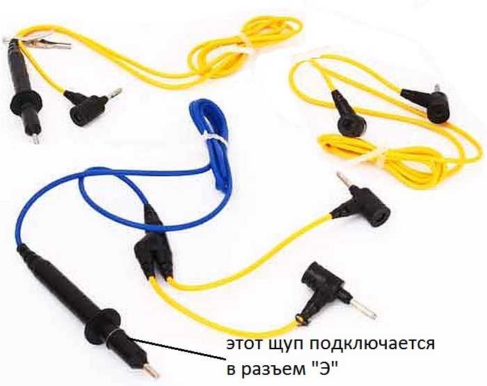
Megohmmeter probes
The probes have stops. When taking measurements with your hands, grip them so that your fingers are up to these stops. This is a prerequisite for safe work (we remember about high voltage).
If it is necessary to check only the insulation resistance without a screen, two single probes are placed - one in the "З" terminal, the other in the "L" terminal. Using crocodile clips at the ends, we connect the probes:
- To the tested wires, if you need to check the breakdown between the cores in the cable.
- To the vein and "ground" if we check the "breakdown to the ground".
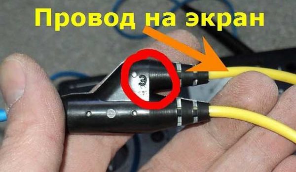
There is a letter "E" - this end is inserted into the socket with the same letter
There are no other combinations. Insulation and its breakdown are checked more often, work with the screen is quite rare, since the shielded cables themselves are rarely used in apartments and private houses. Actually, using a megohmmeter is not particularly difficult. It is only important not to forget about the presence of high voltage and the need remove residual charge after each measurement. This is done by touching the ground wire to the wire just measured. For safety, this wire can be secured to a dry wooden holder.
Measurement process
We set the voltage that the megohmmeter will give out. It is not chosen randomly, but from the table. There are megohmmeters that work with only one voltage, there are those that work with several. The latter, of course, are more convenient, since they can be used to test various devices and circuits. The test voltage is switched by a knob or a button on the front panel of the device.
| Item name | Megohmmeter voltage | Minimum permissible insulation resistance | Notes |
|---|---|---|---|
| Electrical products and devices with voltage up to 50 V | 100 V | Must correspond to the passport, but not less than 0.5 MOhm | Semiconductor devices must be shunted during measurements |
| the same, but with a voltage from 50 V to 100 V | 250 V | ||
| the same, but with a voltage from 100 V to 380 V | 500-1000V | ||
| over 380 V, but not more than 1000 V | 1000-2500V | ||
| Switchgears, boards, conductors | 1000-2500V | Not less than 1 MOhm | Measure each section of the switchgear |
| Electrical wiring, including lighting network | 1000 V | Not less than 0.5 MOhm | In hazardous premises, measurements are taken once a year, in others - once every 3 years |
| Stationary electric stoves | 1000 V | Not less than 1 MOhm | The measurement is carried out on a heated switched off stove at least once a year. |
Before using the megohmmeter, we make sure that there is no voltage on the line - with a tester or an indicator screwdriver. Then, having prepared the device (set the voltage and set the measurement scale on the switches) and connect the probes, remove the grounding from the cable under test (if you remember, it is connected before starting work).
The next stage is to turn on the megohmmeter: on the electronic ones we press the Test button, in the turnouts we turn the handle of the dynamo. In the turnouts we twist until the lamp on the case lights up - this means the required voltage in the circuit is created. In digital at some point the value on the screen stabilizes. The numbers on the screen are insulation resistance. If it is not less than the norm (the averages are indicated in the table, and the exact ones are in the passport for the product), then everything is normal.
How to measure with a megohmmeter
After the measurement is over, stop turning the handle of the megohmmeter or press the button to end the measurement on the electronic model. After that, you can disconnect the probe, remove the residual voltage.
In short, these are all the rules for using a megohmmeter. Let us consider some measurement options in more detail.
Measurement of cable insulation resistance
It is often required to measure the insulation resistance of a cable or wire. If you know how to use a megohmmeter, when checking a single-core cable it will take no more than a minute, with multi-core cables it will take longer. The exact time depends on the number of cores - you will have to check each one.
The test voltage is selected depending on the voltage in the network with which the wire will work. If you plan to use it for 250 or 380 V wiring, you can set 1000 V (see table).
Checking a three-core cable - you can not twist, but measure all pairs
To check the insulation resistance of a single-core cable, we hook one probe to the core, the second to the armor, apply voltage. If there is no armor, we attach the second probe to the "earth" terminal and also apply a test voltage. We look at the readings. If the arrow shows more than 0.5 MΩ, everything is normal, the wire can be used. If less, the insulation is broken and cannot be used.
You can check the multicore cable. Testing is carried out for each core separately. In this case, all other conductors are twisted into one bundle. If, in this case, it is also necessary to check the breakdown to ground, a wire connected to the corresponding bus is also added to the common harness.
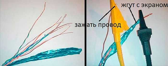
If the cable has a shield, metal sheath or armor, these are also added to the bundle. It is important to ensure good contact when forming a bundle.
The insulation resistance of the socket groups is measured in approximately the same way. Turn off all devices from the sockets, turn off the power on the panel. One probe is installed on the ground terminal, the second - in one of the phases. Test voltage - 1000 V (according to the table). We turn on, check. If the measured resistance is greater than 0.5MΩ, the wiring is OK. We repeat with the second vein.
If the wiring is of the old model - there is only a phase and zero, testing is carried out between two conductors. The parameters are the same.
Check the insulation resistance of the motor
For measurements, the motor is disconnected from the power supply. It is necessary to get to the terminals of the winding. Asynchronous motors up to 1000 V are tested with 500 V.
To check their insulation, we connect one probe to the motor case, the second one is alternately applied to each of the terminals. You can also check the integrity of the connection between the windings. For this check, the probes must be installed on a pair of windings.