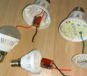
How to connect wires in a junction box
Electricity is an area in which everything must be done correctly and thoroughly. In this regard, many people prefer to figure it out on their own, rather than trust strangers. One of the key points is the connection of the wires in the junction box. The quality of the work depends, firstly, on the correctness of the system, and secondly on the safety - electrical and fire.
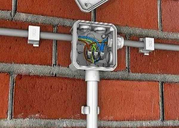
One of the types of junction (soldering, branching) boxes
The content of the article
What is a junction box
From the electrical panel, the wires diverge through the rooms in the house or apartment. In each room, as a rule, there is more than one connection point: there are several outlets and a switch for sure. To standardize the methods of connecting wires and collect them in one place, junction boxes are used (they are also sometimes called branching or junction boxes). They lead cables from all connected devices, the connection of which takes place inside the hollow case.
In order not to look for wiring in the process of the next repair, it is laid according to certain rules, which are spelled out in the PUE - Rules for the Arrangement of Electrical Installations.
Electrical wiring rules
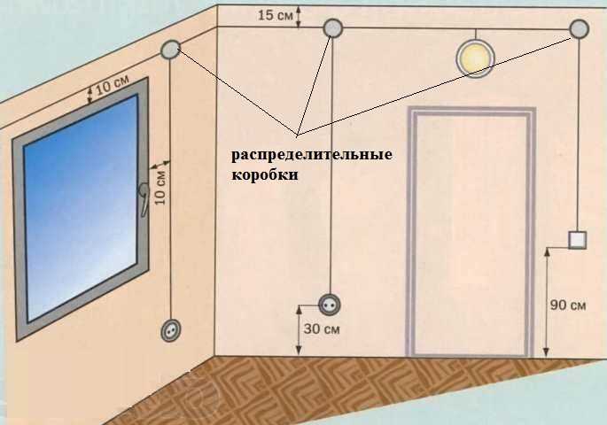
One of the recommendations is to route all connections and branching wires in the junction box. Therefore, the wires are run along the top of the wall, at a distance of 15 cm from the ceiling level. Having reached the branch point, the cable is lowered vertically down. A junction box is installed at the branch point. In it, all the wires are connected according to the required scheme.
According to the type of installation, junction boxes are internal (for concealed installation) and external. A hole is made under the inner ones in the wall, into which the box is built. With this installation, the cover is flush with the finishing material. Sometimes, during the repair process, it is covered with finishing materials. However, such installation is not always possible: the thickness of the walls or decoration does not allow. Then an external box is used, which is fixed directly to the wall surface.
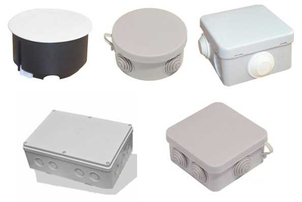
Some forms of junction boxes
The junction box can be round or rectangular in shape. There are usually four conclusions, but there may be more. The terminals have threads or fittings to which it is convenient to attach the corrugated hose. After all, it is in a corrugated hose or a plastic pipe that it is more convenient to lay wires. In this case, replacing the damaged cable will be very easy. First disconnect it in the junction box, then from the consumer (socket or switch), pull and pull it out. Tighten a new one in its place.If it is laid in the old fashioned way - in a gutter, which is then covered with plaster - to replace the cable, you will have to hammer the wall. So this is the recommendation of the PUE, which is definitely worth listening to.
What junction boxes generally give:
- Increased maintainability of the power supply system. Since all connections are accessible, it is easy to locate the damaged area. If the conductors are laid in cable channels (corrugated hoses or pipes), it will be easy to replace the damaged section.
- Most electrical problems arise in the connections, and in this installation option, they can be periodically inspected.
- The installation of junction boxes increases the level of fire safety: all potentially dangerous places are located in certain places.
- Requires less money and labor than cable routing to each outlet.
Ways to connect wires
In the box, the conductors can be connected in different ways. Some of them are more difficult, they are implemented, others are easier, but if they are executed correctly, they all provide the required reliability.
Twisting
The most popular method among folk craftsmen, but the most unreliable. It is not recommended by PUE for use, as it does not provide proper contact, which can lead to overheating and fire. This method can be used as a temporary one, for example, to check the functionality of the assembled circuit, with a mandatory subsequent replacement with a more reliable one.
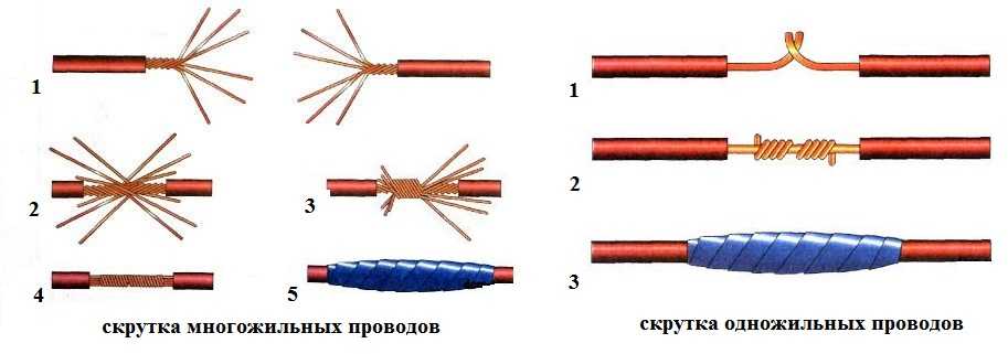
Correct twisting of electrical wires
Even if the connection is temporary, everything must be done according to the rules. The methods of twisting stranded and solid conductors are similar, but have some differences.
When twisting stranded wires, the procedure is as follows:
- the insulation is stripped 4 cm;
- conductors are untwisted by 2 cm (item 1 in the photo);
- are connected to the junction of non-untwisted conductors (position 2);
- the veins are twisted with your fingers (position 3);
- twisting is tightened with pliers or pliers (position 4 in the photo);
- insulated (electrical tape or a heat-shrinkable tube put on before the connection).
Connecting wires in a junction box with one core using twisting is easier. The stripped conductors are crossed and twisted with fingers along the entire length. Then take a tool (pliers and pliers, for example). In one, the conductors are clamped near the insulation, the second is strenuously twisted the conductors, increasing the number of turns. The junction is insulated.
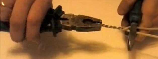
Twist with pliers or pliers
Twist with mounting caps
Twisting is even easier using special caps. With their use, the connection is more reliably insulated, the contact is better. The outer part of such a cap is molded from a plastic that does not support combustion; a metal conical part with a thread is inserted inside. This insert provides a larger contact surface, improving the electrical performance of the connection. This is a great way to connect two (or more) wires without soldering.
Twisting wires with caps is even easier: the insulation is removed by 2 cm, the wires are slightly twisted. A cap is put on them, with effort it is turned several times, until the metal is inside the cap. That's it, the connection is ready.
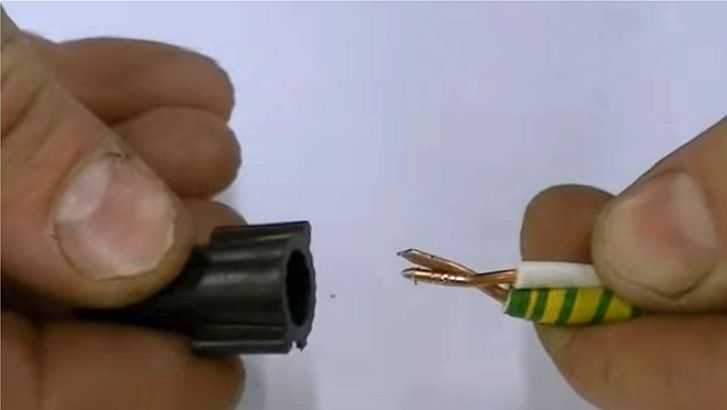
Connecting wires with a cap
Caps are selected depending on the cross-section and the number of conductors that need to be connected. This method is more convenient: it takes less space than ordinary twisting, everything fits more compactly.
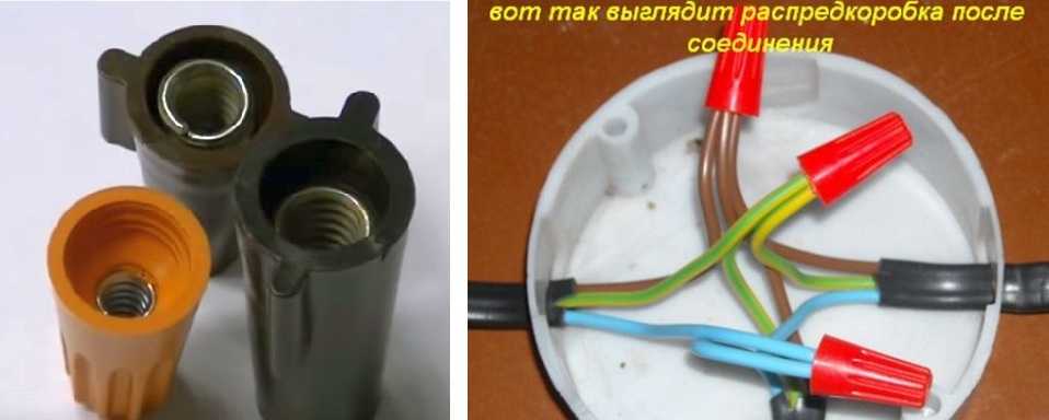
Connecting conductors in a junction box with caps
Soldering
If there is a soldering iron in the house, and you know how to handle it at least a little, it is better to use soldering. Before twisting the wires, they are tinned: a layer of rosin or soldering flux is applied. A heated soldering iron is dipped in rosin, and carried out several times over the part stripped of insulation. A characteristic reddish bloom appears on it.
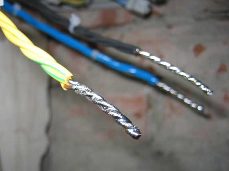
Soldered wires
After that, the wires are twisted as described above (twisting), then they take the tin on a soldering iron, heat the twist until the molten tin begins to flow between the turns, enveloping the connection and ensuring good contact.
Installers do not like this method: it takes a lot of time, but if you make the connection of wires in the junction box for yourself, take the time and effort, but you will sleep peacefully.
Wire welding
If there's inverter welding machine, you can use the connection by welding. This is done on top of the twist. Set the welding current on the machine:
- for a section of 1.5 mm2 about 30 A,
- for a section of 2.5 mm2 - 50 A.
A graphite electrode is used (this is for copper welding).Using grounding pliers, we gently cling to the upper part of the twist, bring the electrode to it from below, touch it briefly, trying to ignite the arc, and remove it. Welding takes place in a split second. After cooling, the junction is insulated. See the video for welding wires in the junction box.
Terminal blocks
Another connection of wires in the junction box is using terminal blocks - terminal blocks, as they are also called. There are different types of pads: with clips and screw, but, in general, the principle of their device is the same. There is a copper sleeve / plate and a wire fastening system. They are designed so that by inserting two / three / four conductors in the right place, you connect them securely. Installation is very simple.
The screw terminal blocks have a plastic housing in which a contact plate is secured. They are of two types: with hidden contacts (new) and with open ones - the old model. In any of them, a conductor stripped of insulation (length up to 1 cm) is inserted into the socket and clamped using a screw and a screwdriver.
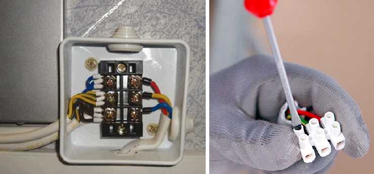
Connection of wires in the junction box using terminal blocks
Their disadvantage is that it is not very convenient to connect a large number of wires in them. The contacts are arranged in pairs, and if you need to connect three or more wires, you have to squeeze two wires into one socket, which is difficult. But they can be used in branches with significant current consumption.
Another type of blocks is Vago terminal blocks. These are quick assembly pads. Two types are mainly used:
- With flat spring mechanism. They are also called disposable, since their reuse, if possible, then with a significant deterioration in the quality of contact. The point is in the internal structure: in the body there is a plate with spring petals. When inserting a conductor (single core only), the petal folds back, clamping the wire. Providing contact, it cuts into the metal. If the conductor, with proper effort, can be pulled out, then the petal will no longer take its previous shape. Therefore, this type is considered disposable. Despite this, the connection is reliable and can be used. There are also special terminal blocks of the same shape, but in a black case. They contain electrical paste inside. These connectors are necessary if you have to connect copper and aluminum, which just do not fit because of the active electrochemical processes that occur between them. The paste prevents oxidation by allowing the two metals to bond easily.

Terminal blocks Vago
- Universal with a lever mechanism. This is perhaps the most convenient connector. Insert the bare conductor (the length is written on the back side), press the small lever. The connection is ready. If necessary, reseal the contact, lift the lever, remove the wire. Conveniently.
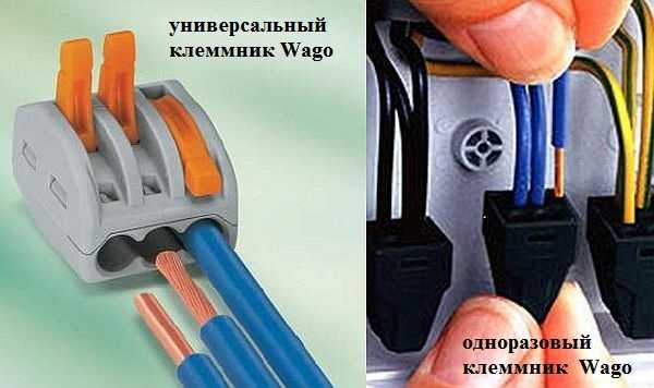
The peculiarity of these terminal blocks is that they can be operated only at low currents: up to 24 A with a copper wire cross-section of 1.5 mm, and up to 32 A with a cross-section of 2.5 mm. When connecting loads with high current consumption, the wiring in the junction box must be connected in a different way.
Crimping
This method is possible with special pliers and a metal sleeve. A sleeve is put on the twist, it is inserted into the pliers and clamped - pressed. This method is just right for lines with high amperage (like welding or soldering). See the video for details. It even contains a junction box model so it will be useful.
Basic wiring schemes
Knowing how to connect the wires in the junction box is not all. It is necessary to figure out which conductors to connect.
How to connect sockets
As a rule, the socket group goes on a separate line. In this case, everything is clear: you have three cables in the box, three (or two) conductors each. Coloring can be the same as in the photo.In this case, usually brown is the phase wire, blue is neutral (neutral), and yellow-green is ground.
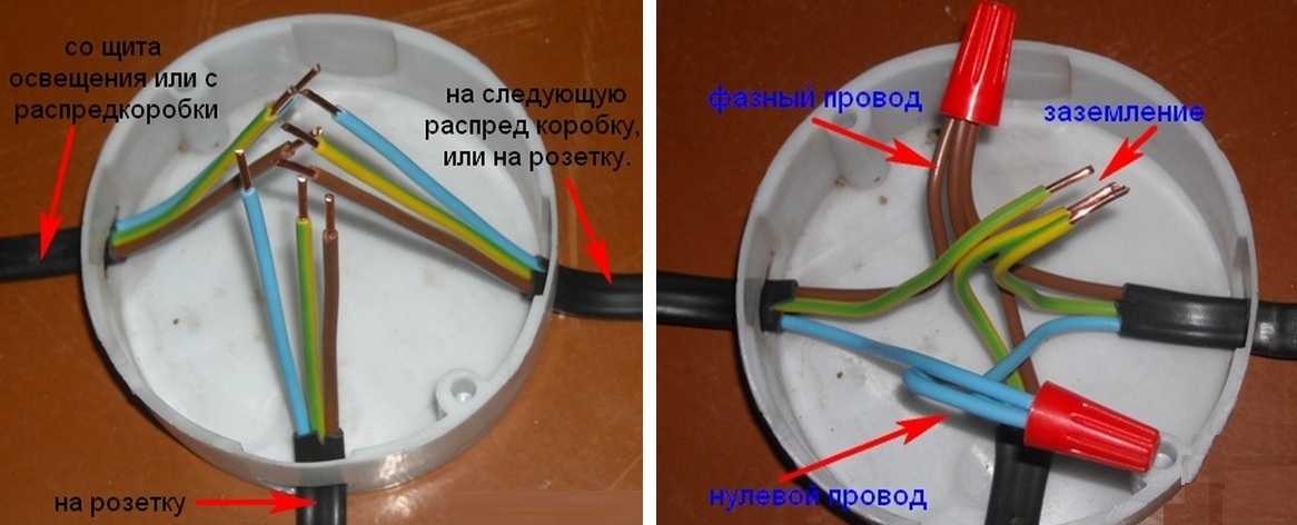
Wiring diagram for the socket in the junction box
In another standard, colors can be red, black and blue. In this case, the phase is red, blue is neutral, green is ground. In any case, the wires are collected by color: all of the same color in one group.
Then they are folded, stretched, cut to the same length. Do not cut short, leave a margin of at least 10 cm so that if necessary, you can reseal the connection. Then the conductors are connected using the selected method.
If only two wires are used (there is no grounding in old buildings), everything is exactly the same, only there are two connections: phase and neutral. By the way, if the wires are of the same color, first find the phase (with a probe or multimeter) and mark it, at least by winding a piece of electrical tape around the insulation.
Connecting a one-button switch
With a switch, things are more complicated. There are also three groups, but their connection is different. there is
- entrance - from another junction box or from a panel;
- from the chandelier;
- from the switch.
How should the circuit work? Power - "phase" - goes to the switch key. From its exit it is fed to the chandelier. In this case, the chandelier will light only when the switch contacts are closed ("on" position). This type of connection is shown in the photo below.
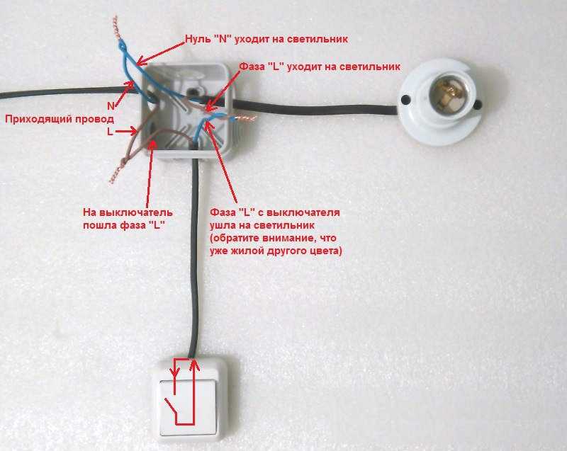
Connecting a one-button switch in a junction box
If you look closely, it turns out that the phase goes to the switch with a light wire. It leaves another contact, but already blue (do not confuse) and connects to the phase wire that goes to the chandelier. Neutral (blue) and ground (if mains) are twisted directly.
Connecting a two-button switch
Connecting wires in a junction box with a two-button switch is a little more complicated. The peculiarity of this circuit is that a three-core cable must be laid to the switch for two groups of lamps (in a circuit without grounding). One wire is connected to the common contact of the switch, the other two to the key outputs. In this case, it is necessary to remember what color the conductor is connected to the common contact.
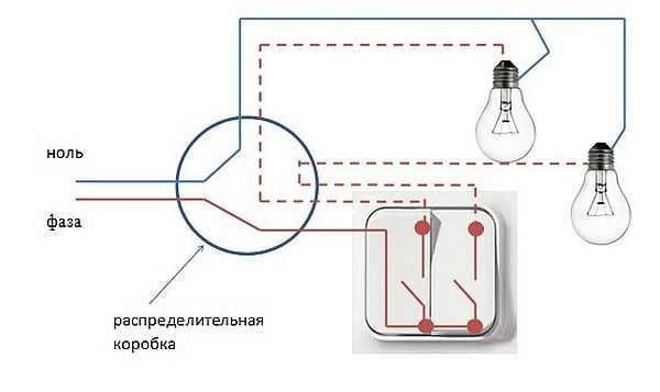
Wiring diagram for a two-button switch
In this case, the phase that has come is connected to the common contact of the switch. The blue wires (neutral) from the input and the two lamps are simply twisted all three together. Remaining wires - phase from the lamps and two wires from the switch. So we connect them in pairs: one wire from the switch to the phase of one lamp, the second output to another lamp.
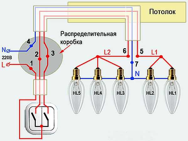
Wiring diagram for a two-button switch
Once again about the connection of wires in the junction box with a two-button switch in video format.