Connection diagrams for fluorescent lamps
With the rise in electricity prices, one has to think about more economical lamps. Some of these use daylight lighting. The connection diagram for fluorescent lamps is not too complicated, so even without special knowledge of electrical engineering you can figure it out.
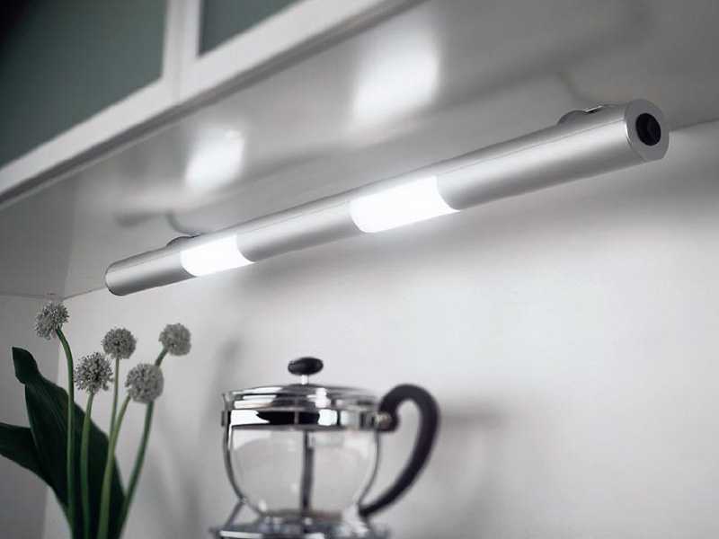
Good illumination and linear dimensions - the advantages of daylight
The content of the article
The principle of operation of a fluorescent lamp
Daylight fixtures use the ability of mercury vapor to emit infrared waves when exposed to electricity. In the range visible to our eyes, this radiation is transferred by phosphor substances.
Therefore, an ordinary fluorescent lamp is a glass bulb, the walls of which are covered with a phosphor. There is also some mercury inside. There are two tungsten electrodes providing electron emission and heating (vaporization) of mercury. The flask is filled with an inert gas, most often argon. Glow begins when mercury vapor is heated to a certain temperature.
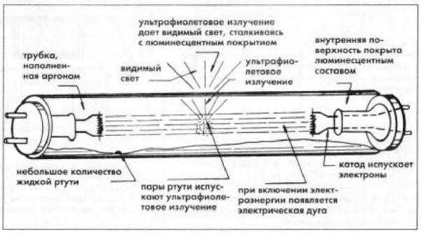
The basic structure of a fluorescent fluorescent lamp
But for the evaporation of mercury, normal mains voltage is not enough. To start working in parallel with the electrodes, start-up control devices (abbreviated as ballast) are turned on. Their task is to create a short-term voltage surge necessary for the onset of glow, and then limit the operating current, preventing it from increasing uncontrollably. These devices - ballasts - are of two types - electromagnetic and electronic. Accordingly, the schemes are different.
Starter circuits
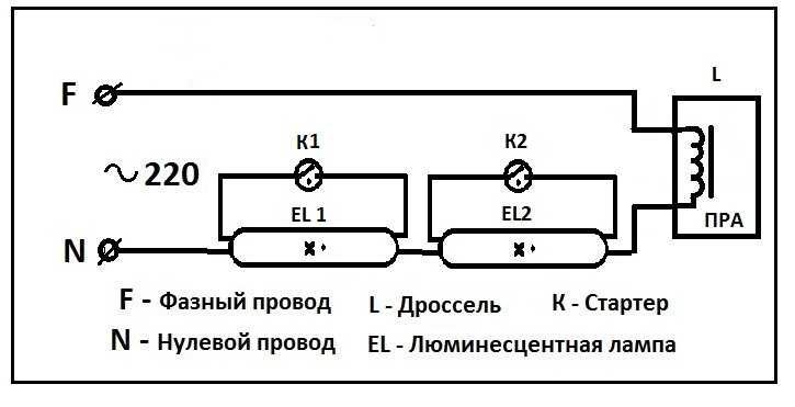
The very first circuits with starters and chokes appeared. These were (and in some versions are) two separate devices, each of which had its own socket. There are also two capacitors in the circuit: one is connected in parallel (to stabilize the voltage), the second is located in the starter housing (increases the duration of the starting pulse). All this "economy" is called electromagnetic ballast.A diagram of a fluorescent lamp with a starter and a choke is shown in the photo below.
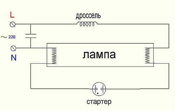
Connection diagram for fluorescent lamps with a starter
This is how it works:
- When the power is turned on, the current flows through the inductor and goes to the first tungsten coil. Further, through the starter, it enters the second spiral and leaves through the zero conductor. At the same time, the tungsten filaments gradually heat up, as do the starter contacts.
- The starter consists of two contacts. One is fixed, the second is movable bimetallic. They are normally open. As the current flows, the bimetallic contact heats up, which causes it to bend. Bent over, it connects to a fixed contact.
- As soon as the contacts are connected, the current in the circuit instantly rises (2-3 times). It is limited only by the throttle.
- Due to a sharp jump, the electrodes are heated very quickly.
- The starter bimetallic plate cools down and breaks the contact.
- At the moment of contact breakage, a sharp voltage jump occurs across the choke (self-induction). This voltage is sufficient for the electrons to break through the argon medium. Ignition occurs and gradually the lamp enters the operating mode. It occurs after all the mercury has evaporated.
The operating voltage in the lamp is lower than the mains voltage for which the starter is designed. Therefore, after ignition, it does not work. In a working lamp, his contacts are open and he does not participate in its work in any way.
This circuit is also called electromagnetic ballast (EMB), and the operation circuit of the electromagnetic ballast is called EMPR. This device is often referred to simply as a choke.
One of EMPRA
The disadvantages of this scheme for connecting a fluorescent lamp are enough:
- pulsating light, which negatively affects the eyes and they quickly get tired;
- noises during start-up and operation;
- impossibility of starting at a low temperature;
- long start - from the moment of switching on, about 1-3 seconds pass.
Two tubes and two chokes
In luminaires for two fluorescent lamps, two sets are connected in series:
- the phase wire is fed to the choke input;
- from the output of the throttle goes to one contact of the lamp 1, from the second contact goes to the starter 1;
- from the starter 1 goes to the second pair of contacts of the same lamp 1, and the free contact is connected to the zero power wire (N);
The second tube is also connected: first the throttle, from it - to one contact of the lamp 2, the second contact of the same group goes to the second starter, the starter output is connected to the second pair of contacts of the lighting device 2 and the free contact is connected to the zero input wire.
Connection diagram for two fluorescent lamps
The same connection diagram for a two-lamp daylight lamp is shown in the video. It may be easier to deal with the wires this way.
Wiring diagram for two lamps from one choke (with two starters)
Practically the most expensive in this circuit are chokes. You can save money and make a two-lamp luminaire with one choke. How - see the video.
Electronic ballast
All the shortcomings of the scheme described above stimulated research. As a result, an electronic ballast circuit was developed. It does not transmit the mains frequency of 50Hz, but high-frequency vibrations (20-60 kHz), thereby removing the blinking light, which is very unpleasant for the eyes.
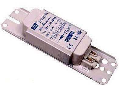
One of the electronic ballasts - electronic ballasts
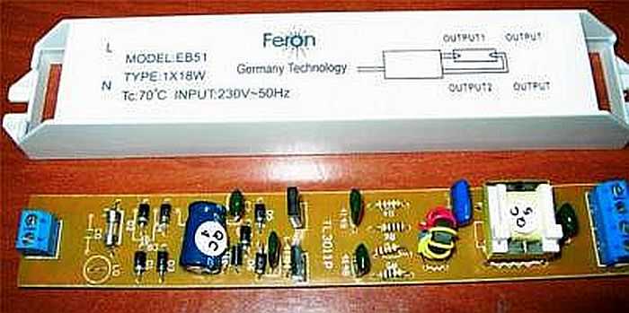
The electronic ballast looks like a small block with removed terminals. Inside there is one printed circuit board on which the entire circuit is assembled. The unit has small dimensions and is mounted in the body of even the smallest luminaire. The parameters are selected so that the start is quick and quiet. No more devices are needed to work. This is the so-called starterless switching circuit.
Each device has a diagram on the back. From it it is immediately clear how many lamps are connected to it. The information is also duplicated in the labels. Indicates the power of the lamps and their number, as well as the technical characteristics of the device. For example, the block in the photo above can only serve one lamp. Its connection diagram is on the right. As you can see, there is nothing complicated. Take the wires, connect them with conductors with the indicated contacts:
- connect the first and second contacts of the block output to one pair of lamp contacts:
- serve the third and fourth for another pair;
- supply power to the entrance.
All. The lamp is working. The circuit for switching on two fluorescent lamps to electronic ballasts is not much more complicated (see the diagram in the photo below).
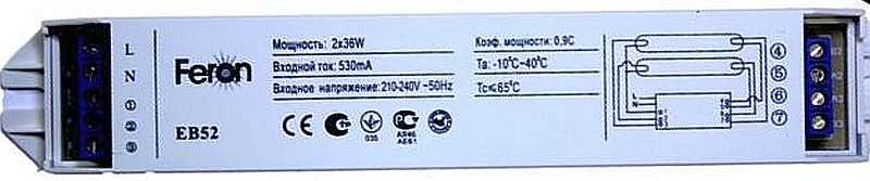
ECG for two fluorescent lamps
The advantages of electronic ballasts are described in the video.
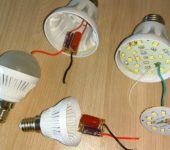
The same device is built into the base of fluorescent lamps with standard sockets, which are also called "economical lamps". This is a similar lighting fixture, only greatly modified.
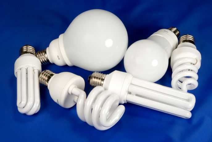
These are also fluorescent lamps, only the shape is different.


Why does LB40-2 Lamps light up and immediately go out?