Collector (mixing unit) for a water heated floor
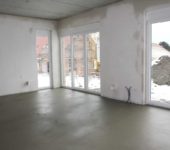
When installing water floor heating, a considerable number of pipes are laid - several sections, which are called contours. All of them are connected to a device that distributes and collects a coolant - a collector for a warm floor.
The content of the article
Purpose and types
The warm water floor is distinguished by a large number of pipe circuits and a low temperature of the coolant circulating in them. Basically, heating of the coolant is required to 35-40 ° C. The only boilers that are capable of operating in this mode are condensing gas boilers. But they are rarely installed. All other types of boilers give out more hot water at the outlet. However, it cannot be started with such a temperature in the circuit - a floor that is too hot is uncomfortable. To reduce the temperature, mixing nodes are also needed. In them, in certain proportions, hot water from the supply and cooled water from the return pipeline is mixed. After that, through the collector for the warm floor, it is supplied to the circuit.
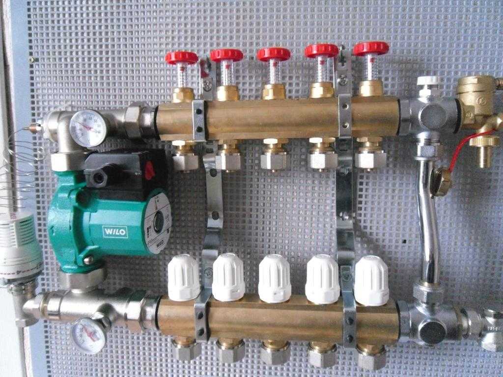
Collector for underfloor heating with mixing unit and circulation pump
So that water of the same temperature enters all circuits, it is supplied to the comb of the warm floor - a device with one inlet and a number of outlets. Such a comb collects cooled water from the circuits, from where it enters the boiler inlet (and partially goes to the mixing unit). This device - the supply and return combs - is also called a collector for a warm floor. It can come with a mixing unit, or maybe only combs without any additional "load".
Materials
The collector for underfloor heating is made of three materials:
- Of stainless steel. The most durable and expensive.
- Brass. Average price category. When using a high-quality alloy, they serve for a very long time.
- Polypropylene. The cheapest. For work with low temperatures (as in this case), polypropylene is a good budget solution.

Collector for underfloor heating for 6 circuits
When installed, the inputs of the underfloor heating circuits are connected to the supply manifold of the collector, and the outputs of the loops are connected to the manifold of the return pipeline. They are connected in pairs - to make it easier to regulate.
Equipment
When water floor heating device it is recommended to make all contours of the same length. This is necessary so that the heat transfer of each loop is the same. It's just a pity that this ideal option is rare. Much more often, there are differences in length, and significant ones.
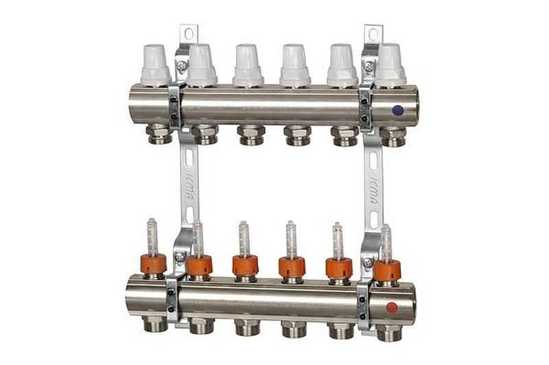
To equalize the heat transfer of all circuits, flow meters are installed on the supply manifold, and control valves on the return manifold. Flowmeters are devices with a transparent plastic cover with graduation applied. In the plastic case, there is a float that marks the speed at which the coolant moves in this loop.
It is clear that the less coolant passes through, the cooler it will be in the room. To correct the temperature regime, the flow rate on each circuit is changed. With this configuration, the collector for underfloor heating is done manually using the control valves installed on the return comb.
The flow rate is changed by turning the knob of the corresponding regulator (in the photo above they are white). To make it easier to navigate, when installing the manifold unit, it is advisable to sign all the contours.
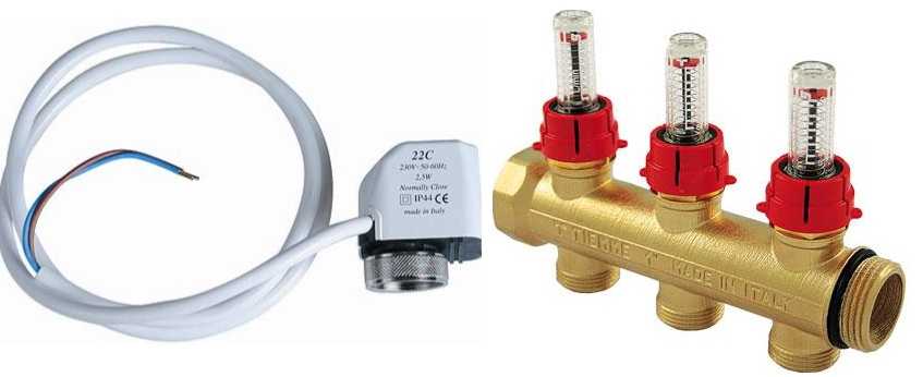
Flowmeters (right) and servo / servo motors (left)
This option is not bad, but you have to adjust the flow rate, which means that you have to manually adjust the temperature. This is not always convenient. To automate the adjustment, servo drives are installed at the inputs. They are paired with room thermostats. Depending on the situation, the servo is commanded to close or open the stream.In this way, maintaining the set temperature is automated.
Mixing unit structure
The mixing group for underfloor heating can be based on a two-way and three-way valve. If the heating system is mixed - with radiators and warm floors, then there is also a circulation pump in the unit. Even if the boiler has its own circulator, it cannot “push through” all the loops of the warm floor. Therefore, they put the second. And the one on the boiler works for the radiators. In this case, this group is sometimes called a pumping and mixing unit.
Three-way valve circuit
A three-way valve is a device that mixes two streams of water. In this case, this is the heated supply water and colder water from the return pipeline.
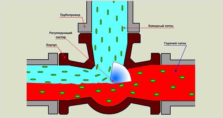
Three-way valve working principle
Inside this valve is a movable regulating sector that regulates the intensity of the flow of colder water. This sector can be controlled by a thermostat, manual or electronic thermostat.
The scheme of the mixing unit on the three-way valve is simple: hot water supply and return flow are connected to the valve outputs, as well as the outlet that goes to the supply manifold of the underfloor heating collector. After the three-way valve, a pump is installed that "presses" the water towards the supply manifold (direction is important!). A little further than the pump, a temperature probe is installed from a thermal head mounted on a three-way valve.
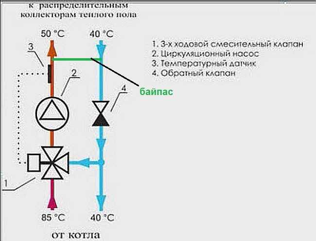
Mixing group diagram for warm water floor on a three-way valve
It all works like this:
- Hot water is supplied from the boiler. At the first moment, it is passed by the valve without admixture.
- The temperature sensor sends information to the valve that the water is hot (the temperature is higher than the set one). The three-way valve opens the return water mixture.
- In this state, the system works until the water temperature reaches the set parameters.
- The three-way valve shuts off the cold water supply.
- In this state, the system works until the water becomes too hot. Then the mix opens again.
The work algorithm is simple and straightforward. But this scheme has a significant drawback - there is a possibility that in case of malfunctions in the underfloor heating circuit, hot water will be supplied directly, without admixture. Since pipes in a warm floor are laid mainly of polymers, they can collapse with prolonged exposure to high temperatures. Unfortunately, this drawback cannot be eliminated in this scheme.
Please note that in the diagram above, a jumper is drawn in green - a bypass. It is needed in order to exclude the possibility of boiler operation without consumption. This situation can arise when all shut-off valves on the underfloor heating manifold are closed. That is, a situation will arise when the flow rate of the coolant will not be at all. In this case, if there is no bypass in the circuit, the boiler may overheat (even overheat for sure) and burn out. In the presence of a bypass, water from the supply through a jumper (made by a pipe, the diameter of which is one step smaller than the main pipe) will be supplied to the boiler inlet. Overheating will not happen, everything will work in normal mode until the flow appears (the temperature in one or more circuits will not drop).
Diagram on a two-way valve
The two-way valve is installed on the boiler feed. A balancing valve is installed on the bridge between the supply and return pipelines. This device is adjustable, it is adjusted depending on the required flow temperature (usually regulated by a hex key). It determines the amount of cold water supplied.
The two-way valve must be installed controlled with a temperature sensor. As in the previous scheme, the sensor is placed after the pump, and the pump drives the coolant towards the comb. Only in this case the intensity of hot water supply from the boiler changes. Accordingly, the temperature of the supplied water at the pump inlet changes (the cold flow is adjusted and stable).
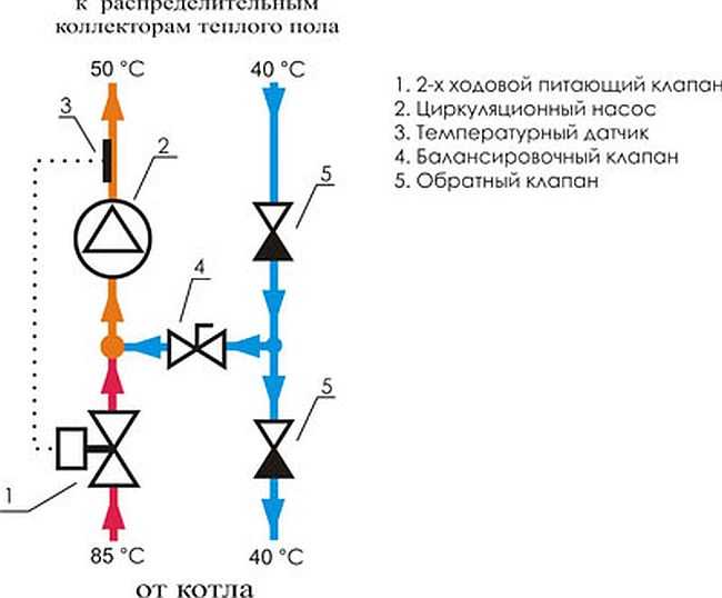
Mixing unit diagram based on a two-way valve
As you can see, cold water is always mixed in such a scheme, so in this scheme it is impossible for water to enter the circuit directly from the boiler. That is, the scheme can be called more reliable. But the mixing group on a two-way valve can provide heating only 150-200 square meters of warm water floors - there are no valves with a higher capacity.
Selection of valve parameters
Both 2-way and 3-way valves are characterized by flow or capacity. This is a value that reflects the amount of coolant that it is able to pass through itself per unit of time. Most often expressed in liters per minute (l / min) or cubic meters per hour (m3/hour).
In general, when designing a system, it is required to make a calculation - to determine the throughput of the underfloor heating circuits, take into account hydraulic resistance, etc. But if the collector for a warm floor is assembled by hand, calculations are extremely rare. Most often they are based on experimental data, and they are as follows:
- valve with a flow rate of up to 2 m3/ hour can provide about 50-100 sq.m. warm floor (100 squares - with a stretch with good insulation).
- if the productivity (sometimes referred to as KVS) is from 2 m3/ hour up to 4 m3/ hour, it is fashionable to put them on systems in which the area of the heated floor is not more than 200 squares;
- for areas over 200 m2, a performance of more than 4 m is required3/ hour, but more often they make two mixing nodes - this is easier.
The materials from which the valves are made - two-way and three-way - brass and stainless steel. When choosing these elements, it is worth taking only branded and proven ones - the work of the entire warm floor depends on their work. There are three clear leaders in quality: Oventrop, Esby, Danfos.
| Name | Connection size | Body / stem material | Performance (KVS) | Maximum water temperature | Price |
|---|---|---|---|---|---|
| Danfoss three-way VMV 15 | 1/2 "inch | brass / stainless steel | 2.5 m3 / h | 120 ° C | 146 € 10690 rub |
| Danfoss three-way VMV-20 | 3/4 "inch | brass / stainless steel | 4 m3 / h | 120 ° C | 152 € 11127 rub |
| Danfoss three-way VMV-25 | 1 "inch | brass / stainless steel | 6.5 m3 / h | 120 ° C | 166 € 12152 rub |
| Esbe three-way VRG 131-15 | 1/2 "inch | brass / composite | 2.5 m3 / h | 110 ° C | 52 € 3806 rub |
| Esbe three-way VRG 131-20 | 3/4 "inch | brass / composite | 4 m3 / h | 110 ° C | 48 € 3514 rub |
| Barberi V07M20NAA | 3/4 "inch | brass | 1.6 m3 / h | adjustment limit - 20-43 ° C | 48 € 3514 rub |
| Barberi V07M25NAA | 1 "inch | brass | 1.6 m3 / h | adjustment limit - 20-43 ° C | 48 € 3514 rub |
| Barberi 46002000MB | 3/4 "inch | brass | 4 m3 / h | 110 ° C | 31 € 2307rub |
| Barberi 46002500MD | 1 "inch | brass | 8 m3 / h | 110 ° C | 40 € £ 2984 |
There is one more parameter by which to choose - the limits of the coolant temperature adjustment. The characteristics usually indicate the plug - the minimum and maximum temperature. If you live in the Middle Lane or to the south, during the off-season, a comfortable room temperature is maintained if the lower control limit is 30 ° C or less (it is already hot at 35 ° C). In this case, the adjustment limits may look like this: 30-55 ° C. For more northern regions or with poor floor insulation, they are taken with an adjustment limit of 35 degrees.
When assembled, the mixing group is installed in front of the underfloor heating manifold. Then the coolant of the required temperature enters the circuit.