How to connect a pass-through switch (light control from two or more points)
Current electricity prices make people think about saving where they hadn't even thought about it before. For example, lighting on the stairs. It doesn't matter if it is in a private or multi-storey building - you still need to pay. Previously, they simply left the light on. Today you think about turning it off, but running up / down is also not joyful. It turns out there is a solution. So that the light does not burn constantly, there are lamp control circuits from several places. That is, one or more luminaires can be switched on and off from several points. Special switches are needed for this. They are called checkpoints. Sometimes there are names "duplicate" or "flip". All this is one type of electrical equipment. They differ from usual in a large number of contacts. Accordingly, the connection diagram of the pass-through switch is more complicated. Nevertheless, you can figure it out.
The content of the article
How the walk-through switch looks and works
If we talk about the front side, the only difference: a barely noticeable arrow on the up and down key.
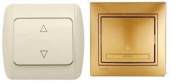
What does a single-key switch look like? See there are double arrows
If we talk about the electrical circuit, everything is also simple: in ordinary switches there are only two contacts, in through-type (also called changeover) there are three contacts, two of which are common. In the circuit, there are always two or more such devices, and with the help of these common wires they are switched.
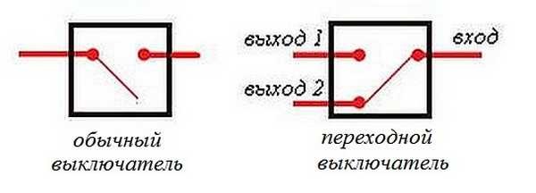
The difference is in the number of contacts
The principle of operation is simple. By changing the position of the key, the input is connected to one of the outputs. That is, these devices have only two operating positions:
- input is connected to output 1;
- input is connected to output 2.
There are no other intermediate provisions. Thanks to this, everything works. Since the contact is switched from one position to another, electricians believe that it is more correct to call them "switches". So a pass-through switch is also this device.
In order not to rely on the presence or absence of arrows on the keys, you need to inspect the contact part. Branded items should have a diagram to help you understand what type of equipment you are holding. It is definitely on the products of the firms Lezard (Lezard), Legrand (Legrand), Viko (Vico). They are often missing on Chinese copies.
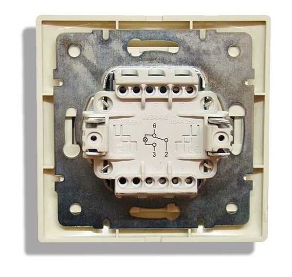
This is what a rocker switch looks like from the rear
If there is no such circuit, look at the terminals (copper contacts in the holes): there should be three of them. But not always on inexpensive copies the terminal that costs one is the input. They are often confused. To find where the common contact is, you need to ring the contacts among themselves at different key positions. This must be done, otherwise nothing will work, and the device itself may burn out.
You will need a tester or multimeter. If you have a multimeter, put it in sound mode - it beeps when there is contact. If a pointer tester is available, ring for a short circuit. Put the probe on one of the contacts, find with which of the two it is ringing (the device beeps or the arrow shows a short circuit - it deviates to the right until it stops). Without changing the position of the probes, change the position of the key. If the short circuit is missing, one of these two is common. Now it remains to check which one. Without switching the key, move one of the probes to the other contact. If there is a short circuit, then the contact from which the probe was not moved is the common one (this is the input).
It may become clearer if you watch the video on how to find the input (common contact) for the pass-through switch.
How to connect the hob is written here, but about installing and turning on the water heater - in this article.
Connection diagram of the pass-through switch from two places
This scheme is convenient in a two-story house on the stairs, in a walk-through room, in a long corridor. You can also use it in the bedroom - turn off the overhead light at the entrance and near the bed (how many times did you have to get up to turn it on / off?).
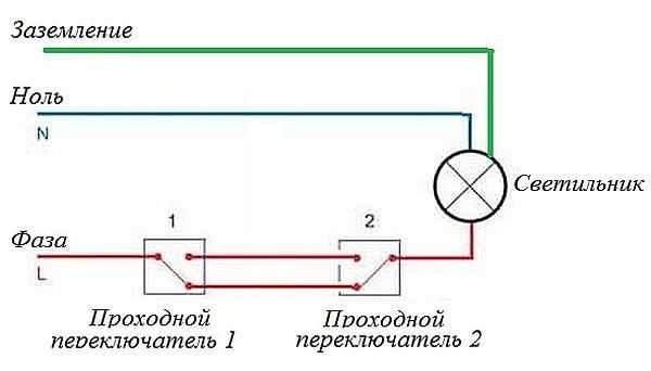
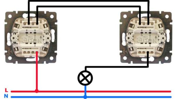
Wiring diagram for switching on the 2-place switch
Zero and earth (if any) are brought directly to the lamp. The phase is fed to the output of the first switch, the input of the second is connected to the free wire of the lamp, the outputs of the two devices are connected to each other.
Looking at this diagram, it is easy to understand how the pass-through switch works. In the position shown in the figure, the lamp is on. By pressing the key of any of the devices, we break the circuit. In the same way, with the off position, by moving any of them to another position, we will close the circuit through one of the jumpers and the lamp will light up.
To make it clearer what and with what to connect, how to lay wires, we will give several images.
Disconnecting wires on the pass-through switch
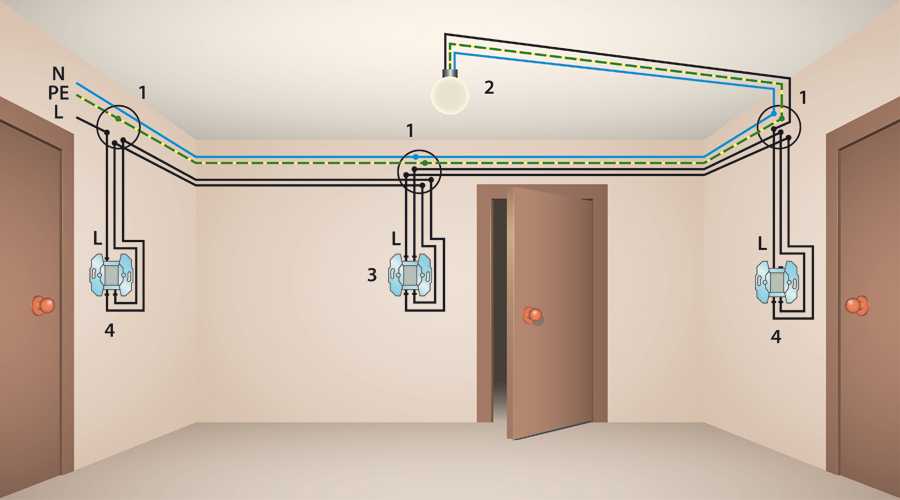
If we talk about the room, then you need to lay the wires approximately as in the photo below. According to modern rules, they should all be located at a distance of 15 cm from the ceiling. They can fit into mounting boxes or trays, the ends of the wires are inserted into mounting boxes. This is convenient: if necessary, you can replace the punched wire. Also, according to the latest standards, all connections are made only in junction boxes and using contactors. If you do twists, then it is better to solder them, and wrap them well with electrical tape on top.
The lamp return wire is connected to the output of the second switch. The white wires are the wires connecting the outputs of both devices.
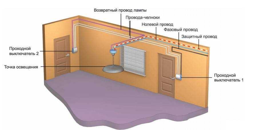
How wires are routed around the room
How to connect everything in the terminal box is described in the video.
How to connect the chandelier yourself, read here.
3-point scheme
To be able to turn on / off the light from three places, it is necessary to buy a cross (cross) switch for two switches. It differs from those described earlier in the presence of two inputs and two outputs. It switches a couple of contacts at once. How everything should be organized, see the figure. If you figured out what is above, it is easy to understand this.
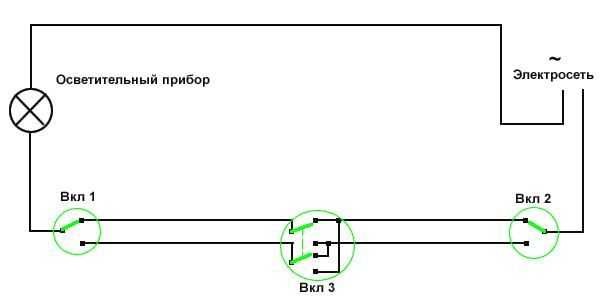
Electrical circuit for lamp control from three points
How to assemble such a scheme? Here is the procedure:
- Zero (and ground, if any) is started directly on the lamp.
- The phase is connected to the input of one of the pass-through switches (with three inputs).
- The input of the second is fed to a free lamp wire.
- Two outputs of one three-contact device are connected to the input of a cross switch (with four inputs).
- Two outputs of the second three-pin device are connected to the second pair of contacts of the switch with four inputs.
The same diagram, but from a different angle - where to connect the wires on the cases.
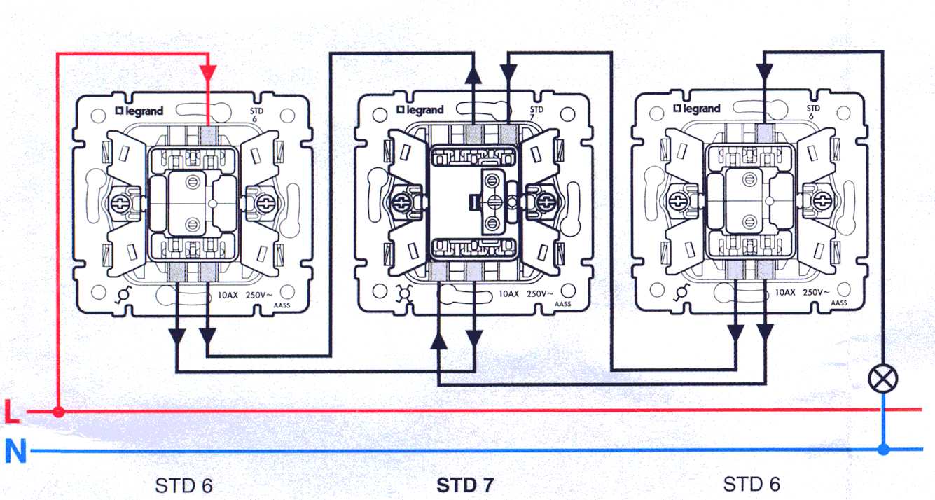
Where to connect the wires
But something like this to plant around the room.
Wiring when controlling a lamp from three places
If you need a circuit with four, five or more points, then it differs only in the number of cross switches (for four inputs / outputs). There are always two switches (with three inputs / outputs) in any circuit - at the very beginning and at the very end of the circuit. All other elements are crossover devices.
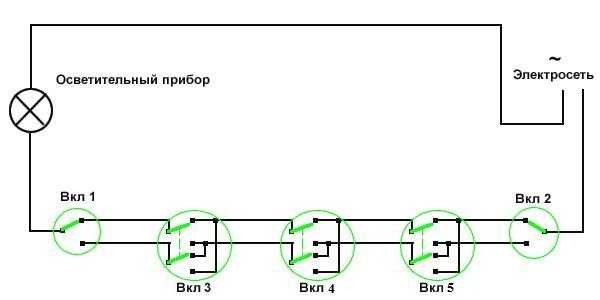
Wiring diagram for 5-point walk-through switches
Remove one "cross", you get a control scheme from four points. Add more - there will already be a scheme for 6 control places.
To finally put everything in your head, watch this video.
ABOUTread the rules for connecting wires in the junction box here.
Two-key pass-through switch: connection diagram
To control the illumination of two lamps (or groups of lamps) from several places from one switch, there are two-key pass-through switches. They have six contacts.If necessary, find common wires according to the same principle as in a conventional device of this type, only you will have to ring a larger number of wires.
The wiring diagram for a 2-key pass-through switch differs only in that there will be more wires: the phase must be supplied to both inputs of the first switch, as well as from two inputs of the second one must go to two lamps (or two groups of lamps, if we are talking about a multi-track chandelier ).
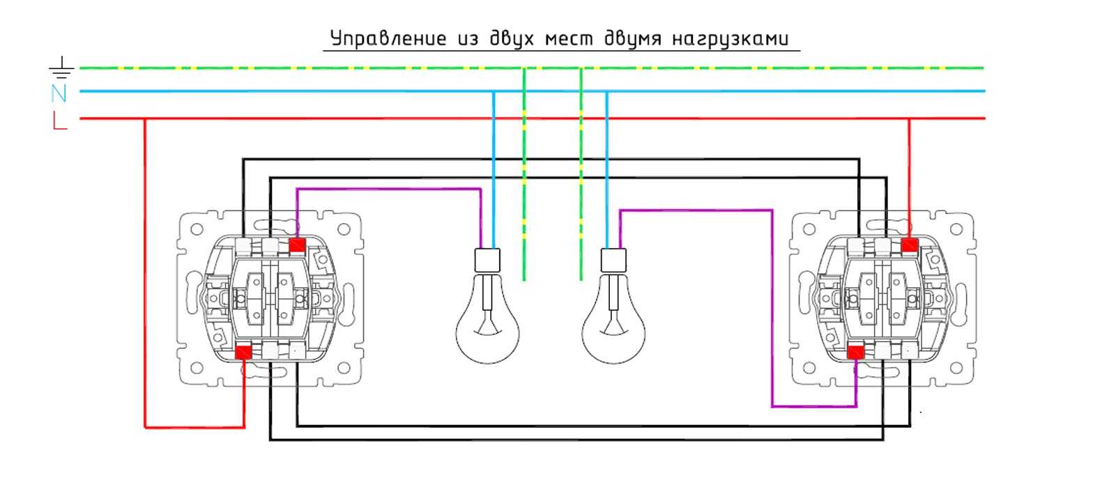
The principle of connecting two-key pass-through switches
If you need to organize control of two light sources from three or more points, you will have to put two cross switches at each point: there are simply no two-key switches. In this case, one pair of contacts is put on one crossroads, the second on the other. And then, if necessary, they are connected to each other. The outputs of both crossings are connected to the last two-key transition switch in the chain.
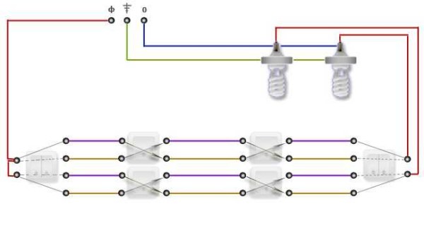
How to manage two lamps from four locations
If you think about it, everything is not so difficult, and the circuit for connecting a 2-point switch is generally simple. Only a lot of wires ...


Thank you, everything is clear and accessible
We try))
Cool. I used to think it was difficult until I saw it. But it turned out to be very simple. I haven’t come across such switches before.