How to connect a single phase motor
Most often, a single-phase 220 V network is supplied to our houses, plots, garages. Therefore, the equipment and all homemade products are made so that they work from this power source. In this article, we will look at how to properly connect a single-phase motor.
The content of the article
Asynchronous versus collector: how to distinguish
In general, the type of engine can be distinguished by the nameplate - the nameplate - on which its data and type are written. But this is only if it was not repaired. After all, under the casing can be anything. So if you're not sure, it's best to determine the type yourself.
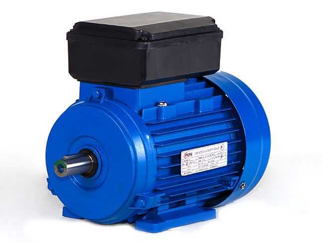
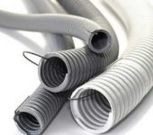
It looks like a new single-phase capacitor motor
How the collector motors are arranged
You can distinguish between asynchronous and collector motors by their structure. The collector must have brushes. They are located near the collector. Another required attribute of this type of engine is the presence of a copper drum, divided into sections.
Such motors are produced only single-phase, they are often installed in household appliances, since they allow you to get a large number of revolutions at the start and after acceleration. They are also convenient in that they easily allow you to change the direction of rotation - you just need to change the polarity. It is also not difficult to organize a change in the speed of rotation - by changing the amplitude of the supply voltage or its cutoff angle. Therefore, similar engines are used in most household and construction equipment.
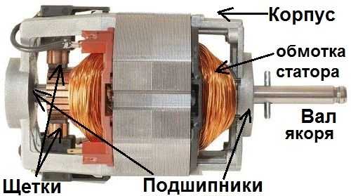
The structure of the collector motor
The disadvantages of collector motors are high operating noise at high revs. Think of a drill, grinder, vacuum cleaner, washing machine, etc. The noise during their work is decent. Brush motors are less noisy at low speeds (washing machine), but not all tools work in this mode.
The second unpleasant moment is the presence of brushes and constant friction leads to the need for regular maintenance. If the current collector is not cleaned, contamination with graphite (from washable brushes) can lead to the fact that adjacent sections in the drum are connected, the motor simply stops working.
Asynchronous
An asynchronous motor has a stator and a rotor, it can be single and three-phase. In this article, we consider the connection of single-phase motors, therefore, we will only talk about them.
Asynchronous motors are distinguished by a low level of noise during operation, therefore they are installed in equipment, the operating noise of which is critical. These are air conditioners, split systems, refrigerators.
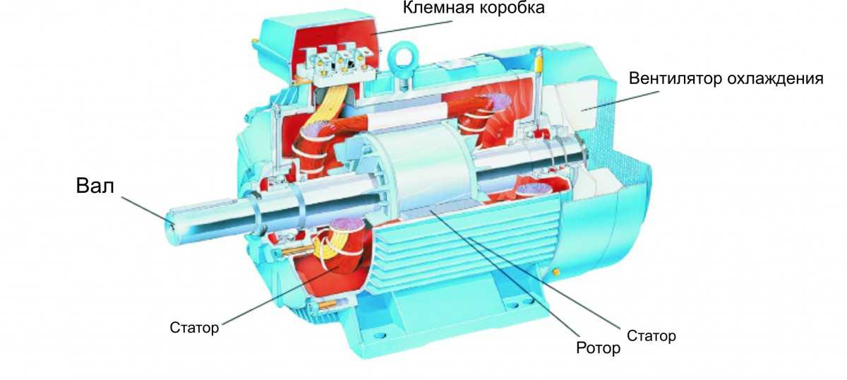
The structure of an asynchronous motor
There are two types of single-phase asynchronous motors - bifilar (with a starting winding) and capacitor. The whole difference is that in bifilar single-phase motors, the starting winding works only until the motor accelerates. After it is turned off by a special device - a centrifugal switch or a start-up relay (in refrigerators). This is necessary, since after overclocking it only reduces the efficiency.
In single-phase capacitor motors, the capacitor winding runs all the time. Two windings - main and auxiliary - are offset relative to each other by 90 °. This allows the direction of rotation to be changed. The capacitor on such motors is usually attached to the body and by this sign it is easy to identify it.
You can more accurately determine the bifilar or capacitor motor in front of you by measuring the resistance of the windings.If the resistance of the auxiliary winding is twice as large (the difference can be even more significant), most likely, this is a bifilar motor and this auxiliary winding is starting, which means that a switch or a starting relay must be present in the circuit. In capacitor motors, both windings are constantly in operation and the connection of a single-phase motor is possible through a conventional button, toggle switch, automatic.
Connection diagrams for single-phase asynchronous motors
With starting winding
To connect a motor with a starting winding, a button is required, in which one of the contacts opens after switching on. These opening contacts will need to be connected to the starting winding. There is such a button in stores - this is PNVS. Her middle contact is closed for the hold time, and the two outer ones remain closed.
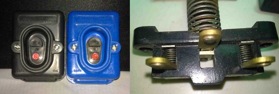
The appearance of the PNVS button and the state of the contacts after the start button is released "
First, using measurements, we determine which winding is working, which is starting. Typically the motor lead has three or four wires.
Consider the three-wire option. In this case, the two windings are already combined, that is, one of the wires is common. We take a tester, measure the resistance between all three pairs. The working one has the least resistance, the average value is the starting winding, and the greatest is the common output (the resistance of two series-connected windings is measured).
If there are four pins, they are called in pairs. Find two pairs. The one in which the resistance is less is the working one, in which the greater is the starting one. After that, we connect one wire from the starting and working windings, we withdraw the common wire. In total, three wires remain (as in the first option):
- one from the working winding - working;
- from the starting winding;
- general.
With these three wires, we continue to work - we use it to connect a single-phase motor.
With all these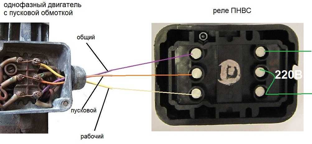
-
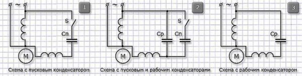
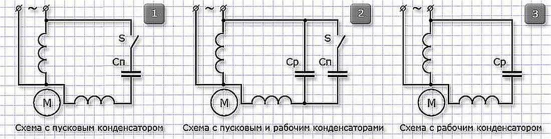
Connection diagrams for a single-phase capacitor motor
The first circuit - with a capacitor in the power supply circuit of the starting winding - starts well, but during operation the power is delivered far from the nominal, but much lower. The switching circuit with a capacitor in the working winding connection circuit has the opposite effect: not very good performance at start-up, but good performance. Accordingly, the first circuit is used in heavy start devices (concrete mixers, for example), and with a working condenser - if good performance is required.
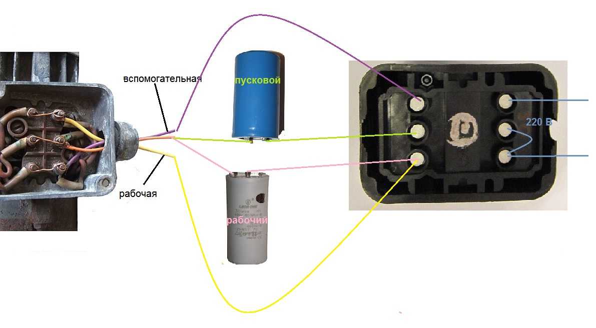
Circuit with two capacitors
There is also a third option for connecting a single-phase motor (asynchronous) - install both capacitors. It turns out something in between the options described above. This scheme is implemented most often. It is in the figure above in the middle or in the photo below in more detail. When organizing this circuit, a PNVS type button is also needed, which will connect the capacitor only not at the start time, while the motor "accelerates". Then two windings will remain connected, and the auxiliary one through the capacitor.

Connecting a single-phase motor: a circuit with two capacitors - working and starting
When implementing other schemes - with one capacitor - you will need an ordinary button, automatic machine or toggle switch. Everything connects there simply.
Selection of capacitors
There is a rather complicated formula by which you can calculate the required capacity accurately, but it is quite possible to get by with the recommendations that have been derived from many experiments:
- the working capacitor is taken at the rate of 70-80 μF per 1 kW of engine power;
- launcher - 2-3 times more.
The operating voltage of these capacitors must be 1.5 times higher than the mains voltage, that is, for a 220 volt network we take capacitors with an operating voltage of 330 V and higher. And to make the start easier, look for a special capacitor for the starting circuit. They have the words Start or Starting in the marking, but you can take the usual ones.
Changing the direction of the motor
If, after connecting, the motor works, but the shaft rotates in the wrong direction, which you want, you can change this direction. This is done by changing the windings of the auxiliary winding.When the circuit was assembled, one of the wires was fed to the button, the second was connected to the wire from the working winding and the common was brought out. This is where you need to transfer the conductors.
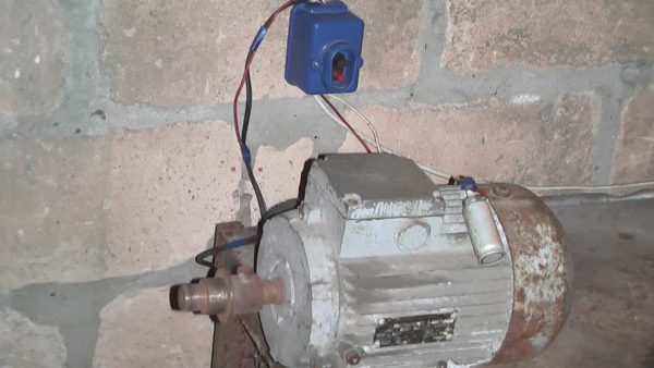
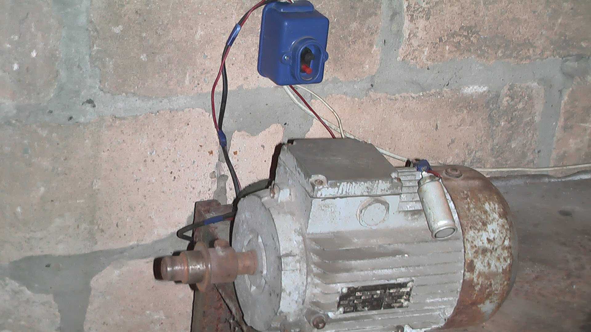
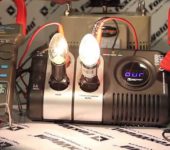
How things might look in practice


need to know…
Motor with starting winding. Starts without a capacitor. Rotates in one direction only. The other is buzzing. Do I need to run it through a capacitor or will it not burn out anyway? (Sharpener with pasted skin.)
men. give advice. compressor engine 2.2 kW. to parents a centrifugal switch. failed to buy. can't find one. compressor Chinese. verc. how to bypass the centrifugal switch on the kmpressore. that you can put what would work as before. turned on and turned on. job thanks. or maybe someone from Kirovograd is there and can fix everything. $$$. thanks in advance.
Can you please tell me the starting winding is burnt out, is the working rate to be used, or is that all ...?
You can try rewinding the starting winding.
Useful article. Thank you so much. But I had several questions that I did not fully understand.
On another site I read the following:
For motors of the first type (bifilar), the starting winding is turned on through the capacitor only at the moment of starting and after the engine has reached its normal speed of rotation, it is disconnected from the network. The motor continues to run with one working winding. The capacitor size is usually indicated on the motor nameplate and depends on its design.
1. In bifilar motors, the starting winding is also switched on through a capacitor, which was not written about in this article, or is it misleading on another site?
2. It is not clear why when we connect a motor with a starting winding through a PNVS relay, the figure in the engine armor shows as if we are connecting a 220/380 delta / star asynchronous three-phase motor. Is there a photo of a single-phase boron motor with a starting winding, in which 3 or 4 wires, starting and working windings will be output? I would like to see how the three wires from the PNVS relay button will connect to these wires.
Help me to understand. El / engine: AVE-071-4cm, 220v, 180w, 1.3A, 1350rpm. Three wires come out: C1, C2, P2. In the C1-P2 circuit, two elements marked 10MV (0482) 1W are connected in series (what is this?). The engine is started up, then not, and in different directions of rotation. How to connect correctly?
the working capacitor is taken at the rate of 0.7-0.8 μF per 1 kW of engine power ;? The capacitor is taken at the rate of 7-8 microfarads per 100 W of engine power, respectively, for 1 kW there will be 70-80 microfarads
Hello! 2.2 kW engine burned out working capacitor no marking what is its capacity?
As far as I know, the capacitance of the capacitor also depends on the engine speed. If we proceed only from power, then for a 2.2 kW motor, a capacitor with a capacity of 150 to 180 μF is required.
friends well, explain more clearly. and then three wires and I do not understand how to determine where the starting and working ones are. the wire . if you take two reasons and measure which of the two should be named? that's the point. and so on in other engines.you can show or draw it so that the student understands. on the diagrams it is not clear where the connection of the two ends of the windings is in the motor or at the output. the explanation speaks of three wires, and in the circuit there are two windings, hence four ends. as in motors with four wire outputs. probably you need to show the contours for the button motor, etc. I have a motor with three outputs, but it does not indicate what to connect the capacitor. And the explanations of the diagram show capacitors. I started with a button without a capacitor and. it turned out but the quality is not yet known. so it turns out that from your explanations in this matter nothing to understand. or not my option. so what's next? but you can show everything in turn and much shorter. thanks for the schemes. for Dummies.
Of the three wires, one is common. The starting winding has less resistance than the working one.
excellent article, concise and accessible.
cool article - everything is clear
Thank you