Designation of electrical elements in the diagrams
To understand what is specifically drawn on a diagram or drawing, you need to know the decoding of those icons that are on it. This recognition is also called drawing reading. And to facilitate this lesson, almost all elements have their own conventional icons. Almost, because the standards have not been updated for a long time and some elements draw everyone as best they can. But, for the most part, the symbols in electrical circuits are in the regulatory documents.
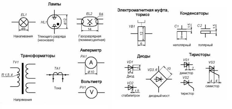
Symbols in electrical circuits: lamps, transformers, measuring instruments, the main element base
The content of the article
Normative base
There are about a dozen types of electrical circuits, the number of different elements that can be found there is in the tens if not hundreds. To facilitate the recognition of these elements, uniform symbols have been introduced in electrical circuits. All rules are spelled out in GOSTs. There are many of these standards, but the basic information is in the following standards:
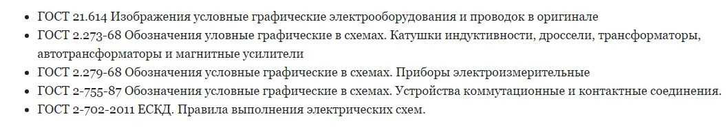
Normative documents in which graphic designations of the element base of electrical circuits are prescribed
Studying GOSTs is a useful business, but it takes time, which not everyone has in sufficient quantity. Therefore, in the article we will give the symbols in electrical circuits - the main element base for creating drawings and wiring diagrams, circuit diagrams of devices.
Designation of electrical elements in the diagrams
Some experts, having carefully looked at the diagram, can tell what it is and how it works. Some may even immediately give out possible problems that may arise during operation. It's simple - they know the circuitry and the element base well, and are also well versed in the symbols of circuit elements. Such a skill has been developed over the years, and, for “dummies”, it is important to remember the most common ones to begin with.
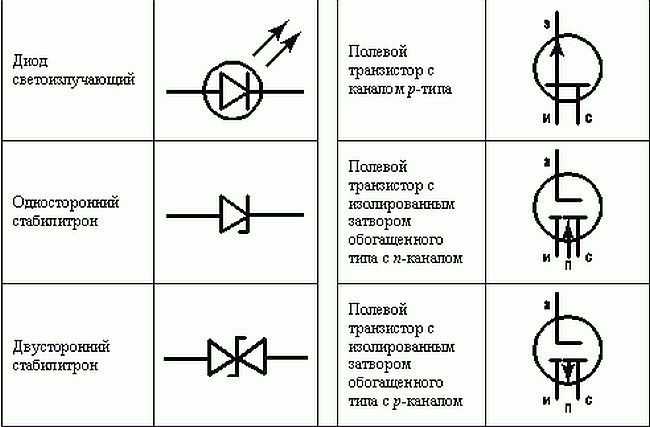
Designation of LED, zener diode, transistor (different types)
Electrical panels, cabinets, boxes
On the power supply diagrams of a house or apartment, there will definitely be a designation electrical panel or cabinet. In apartments, the terminal device is mainly installed there, since the wiring does not go further. In houses, they can design the installation of a branching electrical cabinet - if a route goes from it to the lighting of other buildings located at some distance from the house - baths, summer kitchen, guest house. These other designations are in the next picture.
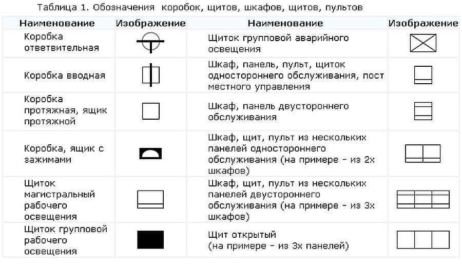
Designation of electrical elements on the diagrams: cabinets, shields, consoles
If we talk about the images of the "filling" of electrical panels, it is also standardized. There are symbols for RCDs, circuit breakers, buttons, current and voltage transformers and some other elements. They are shown in the following table (there are two pages in the table, scroll by clicking on the word "Next")
| room | Name | Image on the diagram |
|---|---|---|
| 1 | Circuit breaker (automatic) | 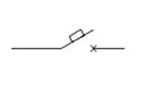 |
| 2 | Switch (load switch) | 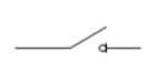 |
| 3 | Thermal relay (overheating protection) | 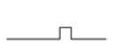 |
| 4 | RCD (residual current device) | 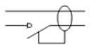 |
| 5 | Differential automatic machine (difavtomat) | 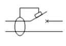 |
| 6 | Fuse |  |
| 7 | Switch (switch) with fuse | 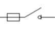 |
| 8 | Circuit breaker with built-in thermal relay (for motor protection) | 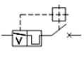 |
| 9 | Current transformer | 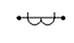 |
| 10 | Voltage transformer | 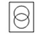 |
| 11 | Electricity meter | 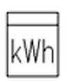 |
| 12 | Frequency converter | 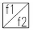 |
| 13 | Button with automatic opening of contacts after pressing | 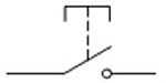 |
| 14 | Button with contact opening when pressed again | 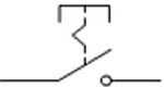 |
| 15 | Button with a special switch for shutdown (stop, for example) | 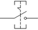 |
Element base for wiring diagrams
When drawing up or reading a diagram, the designations of wires, terminals, grounding, zero, etc. are also useful. This is what a novice electrician simply needs or in order to understand what is shown in the drawing and in what sequence its elements are connected.
| room | Name | Designation of electrical elements in the diagrams |
|---|---|---|
| 1 | Phase conductor | 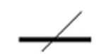 |
| 2 | Neutral (zero working) N | 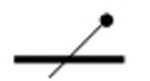 |
| 3 | Protective conductor (earth) PE | 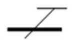 |
| 4 | Combined protective and neutral conductors PEN | 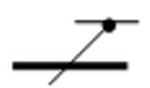 |
| 5 | Electric communication line, buses | |
| 6 | Bus (if it needs to be highlighted) | 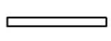 |
| 7 | Taps from tires (made by soldering) | 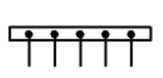 |
An example of using the above graphics is in the following diagram. Thanks to the letter designations, everything is clear even without graphics, but the duplication of information in the diagrams has never been superfluous.
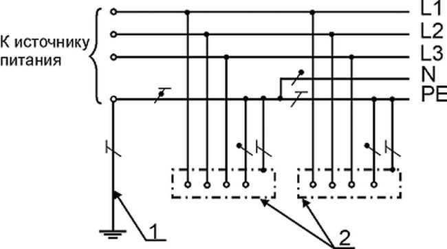
An example of a power supply diagram and a graphic representation of the wires on it
Image of sockets
On the wiring diagram, the locations of the sockets and switches should be marked. There are many types of sockets - 220 V, 380 V, hidden and open installation types, with different numbers of seats, waterproof, etc. To give the designation of each is too long and unnecessary. It is important to remember how the main groups are depicted, and the number of contact groups is determined by strokes.
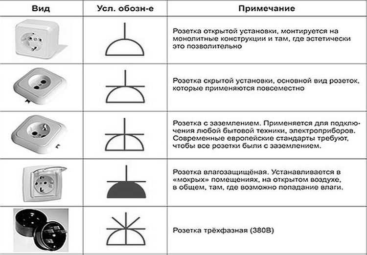
Outlet designation in drawings
Sockets for a single-phase 220 V network are indicated on the diagrams in the form of a semicircle with one or more segments sticking up. The number of segments - the number of sockets on one body (pictured below). If only one plug can be plugged into the outlet, one segment is drawn up, if two - two, etc.
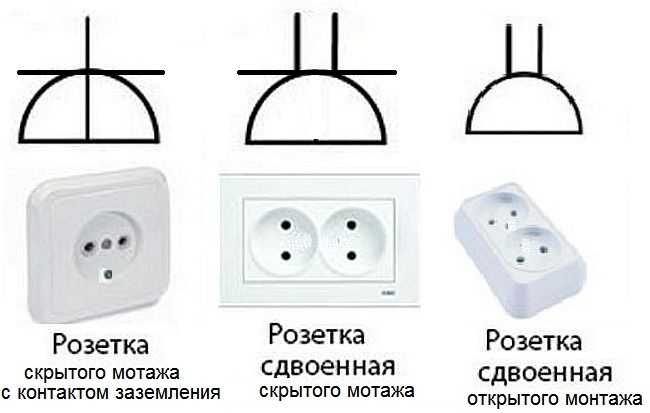
Symbols of sockets in electrical circuits
If you look closely at the images, notice that the conditional image on the right does not have a horizontal bar that separates the two parts of the icon. This feature indicates that the socket is flush-mounted, that is, it is necessary to make a hole in the wall for it, install a socket outlet, etc. The option on the right is for surface mounting. A non-conductive substrate is attached to the wall, the socket itself is attached to it.
Also note that the bottom of the left schematic is crossed out with a vertical line. This means the presence of a protective contact to which the ground is connected. Installation of sockets with grounding is required when turning on complex household appliances such as washing or dishwasher, ovens, etc.
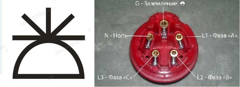
Designation of a three-phase outlet in the drawings
You will not confuse with anything the symbol of a three-phase outlet (380 V). The number of segments sticking up is equal to the number of conductors that are connected to this device - three phases, zero and ground. Total five.
It happens that the bottom of the image is painted black (dark). This means that the socket is waterproof. These are placed outdoors, in rooms with high humidity (saunas, swimming pools, etc.).
Displaying switches
The schematic designation of the switches looks like a small circle with one or more L- or T-shaped branches. Taps in the shape of the letter "L" designate a surface-mounted switch, with the letter "T" - for flush-mounted installation. The number of taps displays the number of keys on this device.
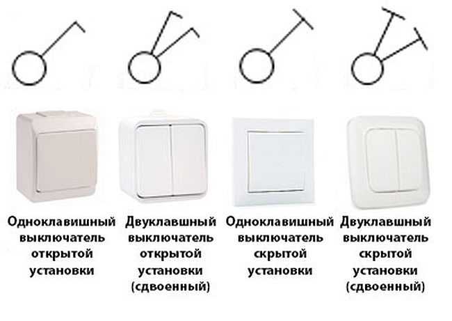
Conventional graphic designations of switches on electrical circuits
In addition to the usual ones, they can stand pass-through switches - to enable / disable one light source from multiple points. Two letters "G" are added to the same small circle from opposite sides. This is the designation for a one-key pass-through switch.
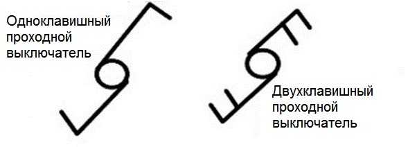
What does a schematic representation of pass-through switches look like?
Unlike conventional switches, in these, when using two-key models, another bar is added, parallel to the upper one.
Lamps and lamps
Lamps have their own designations. Moreover, fluorescent lamps and incandescent lamps differ. The diagrams even show the shape and size of the fixtures. In this case, you just need to remember how each of the types of lamps looks on the diagram.
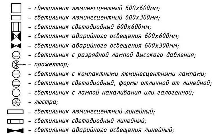
Image of luminaires in diagrams and drawings
Radioelements
When reading the schematic diagrams of devices, you need to know the symbols of diodes, resistors, and other similar elements.
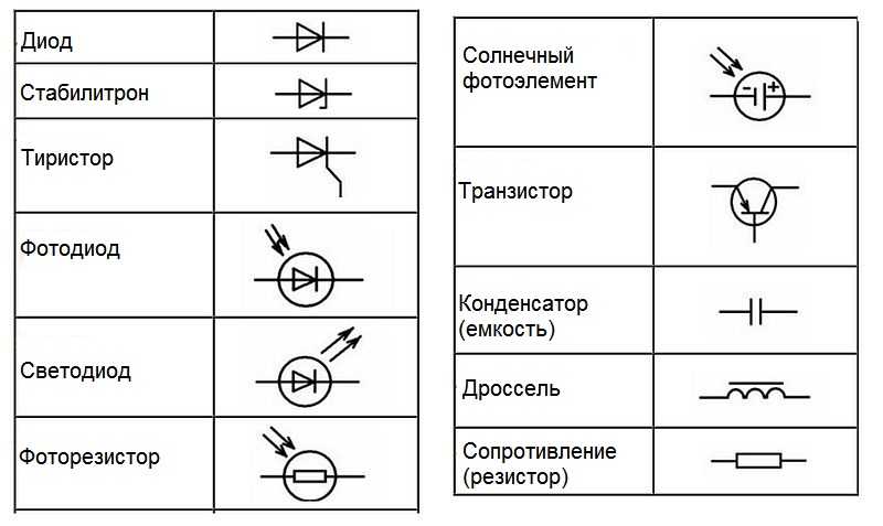
Symbols of radioelements in the drawings
Knowledge of conventional graphic elements will help you read almost any diagram - any device or wiring. The denominations of the required parts are sometimes put down next to the image, but in large multi-element circuits they are written in a separate table. It contains letter designations of circuit elements and denominations.
Letter designations
In addition to the fact that the elements on the diagrams have conventional graphic names, they have letter designations, and they are also standardized (GOST 7624-55).
| Electrical circuit element name | Letter designation | |
|---|---|---|
| 1 | Switch, controller, switch | IN |
| 2 | Power generator | D |
| 3 | Diode | D |
| 4 | Rectifier | Bn |
| 5 | Sound signaling (bell, siren) | Sv |
| 6 | Button | Kn |
| 7 | Incandescent lamp | L |
| 8 | Electrical engine | M |
| 9 | Fuse | Etc |
| 10 | Contactor, magnetic starter | TO |
| 11 | Relay | R |
| 12 | Transformer (autotransformer) | Tr |
| 13 | Plug connector | Sh |
| 14 | Electromagnet | Em |
| 15 | Resistor | R |
| 16 | Capacitor | FROM |
| 17 | Inductor | L |
| 18 | Control button | Ku |
| 19 | Terminal switch | Kv |
| 20 | Throttle | Dr |
| 21 | Telephone | T |
| 22 | Microphone | Mk |
| 23 | Speaker | Gr |
| 24 | Battery (galvanic cell) | B |
| 25 | Main engine | Dg |
| 26 | Cooling pump motor | Before |
Please note that in most cases Russian letters are used, but the resistor, capacitor and inductor are indicated by Latin letters.
There is one subtlety in the designation of the relay. They are of different types, respectively marked:
- current relay - RT;
- power - RM;
- voltage - RN;
- time - PB;
- resistance - RS;
- index - RU;
- intermediate - RP;
- gas - RG;
- with a time delay - RTV.
Basically, these are only the most conventional symbols in electrical circuits. But you can now understand most of the drawings and plans. If you need to know the images of more rare elements, study GOSTs.


The socket designation is incorrect !!! A grounding conductor is a horizontal bar. A hidden / open installation is a vertical bar within a semicircle. GOST 21.614-88
For a "connoisseur" of the above post - GOST 21.614-88 DOES NOT WORK !!! It is not legal to refer to it! See GOST replacing it.